3 sdi-12 interface, 4 diagnostic leds – Optiquest iRIS 320 User Manual
Page 70
iRIS 220 / iRIS 320, V1.19 User Guide - 68
68
iQuest (NZ) Ltd - PO Box 15169, Hamilton, New Zealand Tel: +64 7 857-0810 Fax: +64 7 857-0811 Email: [email protected]
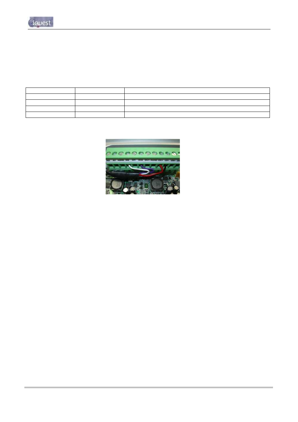
13.3 SDI-12 Interface
The original (PCB revision 1.1) iRIS 320 / iRIS 320V models supported the connection of SDI-12 instruments
via a psuedo SDI-12 interface. This requires the installation of a small interface adaptor that enables the
iRIS to use two of its digital I/O (DI2 and DO2) to provide the SDI-12 communication. The photograph below
shows how the SDI-12 interface adaptor should be installed. The interface wire colours and their functions
with respect to the SDI-12 bus are:
Interface Wire
I/O Terminal
SDI-12 Bus Function
Red
12V+
+12V Supply
Black
GND
0V (Ground)
Purple
DO2
White
DI2
Data
Figure 16 - Legacy SDI-12 Interface Connections
NOTE: The DI2 input debounce link must be removed for the SDI-12 function to work correctly. See
the section above (Section 13.2) shows the link positions on the V1.1 PCB.
13.4 Diagnostic LEDs
The iRIS has several internal LED indicators that are useful for diagnostic purposes. Please note that these
indicators are only active in certain power management modes (see the features section 2.8.4 for details on
power management).
NOTE: The diagnostic LEDs are only visible if the PCB (printed circuit board) is exposed. For the
iRIS 220, the electronic assembly must be removed from the case. For the iRIS 320, the front of the
case must be opened.
232 RX
Flashes green when data is received from the RS232 port.
232 TX
Flashes green when data is transmitted out the RS232 port.
SKT A RX
Flashes green when ASCII data is received via the wireless modem on socket A.
SKT A TX
Flashes green when ASCII data is transmitted via the wireless modem on socket A.
SKT B RX
Flashes green when a System DO
(binary) data packet is received via the wireless
modem on socket B.
SKT B TX
Flashes green when a System DO
(binary) data packet is transmitted via the
wireless modem on socket B.
DIGIN #1
Illuminated orange when Digital Input #1 is active (pulled down to 0V).
DIGIN #2
Illuminated orange when Digital Input #2 is active (pulled down to 0V).