Wiser2400.plus – OTC Wireless 802.11 Wireless Serial Solutions WiSER2400.IP User Manual
Page 8
WiSER 2400 Technical Manual
Version 2.16
Copyright 2001-2005, OTC Wireless, Inc. All Rights Reserved
Page 8 of 32
WiSER2400.Plus
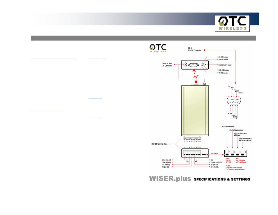
This section describes the signals expected on the mini-Phoenix connector
pins.
10-pin mini-Phoenix terminal:
Pin:
1.
DATA+(RS-485)
2.
DATA- (RS-485)
3.
N/C
4.
TX+ (RS-422)
5.
TX- (RS-422)
6.
RX+ (RS-422)
7.
RX- (RS-422)
8.
N/C
9.
V+ (Up to +32 VDC)
10.
GROUND
DB 9 male connector:
Pin:
1.
DCD
2.
RXD
3.
TXD
4.
DTR
5.
Ground
6.
DSR
7.
RTS
8.
CTS
9.
-
Dip Switch:
Location (from left to right)
1.
#RS232/485 selector
2.
#Full/Half duplex selector
3.
120 ohm termination -- 422
RX pair
4.
120 ohm termination -- 422
TX pair or 485 pair.
For 1 & 2:
The level up position is high.
The level down position is low.
For 3 & 4:
The level up position is without
terminator.
The level down position is with
terminator.
Fig. 4
WiSER2400.Plus