Orion SKYQUEST XT10 CLASSIC User Manual
Page 6
6
used under dark skies and a bright setting is used under light-
polluted skies or daylight.
At the end of your observing session, be sure to turn the power
knob counterclockwise until it clicks off. When the white dots
on the EZ Finder II’s body and power knob are lined up, the EZ
Finder II is turned off.
installing the correctension (Xt) Friction
optimization system
Perhaps the most exciting feature of the SkyQuest Dobsonians
is the CorrecTension Friction Optimization system. Because of
their light weight, 10" and smaller Dobsonians have always
been plagued by insufficient friction on the altitude bearing
surfaces. As a result, such telescopes move up and down
much too freely. This causes problems when the observer tries
to accurately center and track an object for viewing, especially
at higher powers. Also, the telescope becomes very sensitive
to balance, requiring additional equipment such as counter-
weight systems or adjustable side bearings to compensate.
SkyQuest Dobsonians employ a simple yet effective remedy
for the friction problem that obviates the need for such cum-
bersome countermeasures. CorrecTension Friction Optimization
utilizes a spring coil to “pull” the tube assembly down onto the
altitude bearing pads, thereby increasing the friction by just
the right amount. With CorrecTension, you can change eye-
pieces, or add a barlow lens or solar filter without having to
tediously adjust the telescope’s balance as you would with
other Dobsonians. The altitude friction will roughly equal the
azimuth friction, ensuring optimal performance.
To install the CorrecTension assembly, follow these steps while
referring to Figure 7:
1. Put one of the black nylon spacers on a black Phillips-head
screw. The spacer should be oriented so the narrow end
seats against the head of the screw. Slip one of the black
1/4" washers over the end of the screw. Now, thread the
screw into the hole in the base side panel just below the
cradle. The screw will thread into the preinstalled insert in
the hole. Use a Phillips screwdriver to tighten the screw.
Repeat this procedure on the opposite side panel.
2. Next, insert one of the screws with a round plastic knob
attached through the end ring of one of the springs. Slip
a black nylon spacer onto the screw. Orient the spacer so
the narrow end is closest to the knob. Thread the entire
assembly into the hole in the center of the telescope’s
altitude side bearing until tight. The end ring of the spring
should seat onto the narrow end of the spacer. Repeat this
procedure for the other altitude side bearing.
3 Attach a pull loop to the free end of each spring. Slide the loop
through the opening in the ring on the end of the spring.
4. Now, pull each spring down using the pull loop, and posi-
tion the spring’s end ring over the head of the Phillips
screw (installed in Step 1) and onto the narrow part of the
nylon spacer, as shown in Figure 8b. You needn’t attach
both springs simultaneously; one at a time is fine.
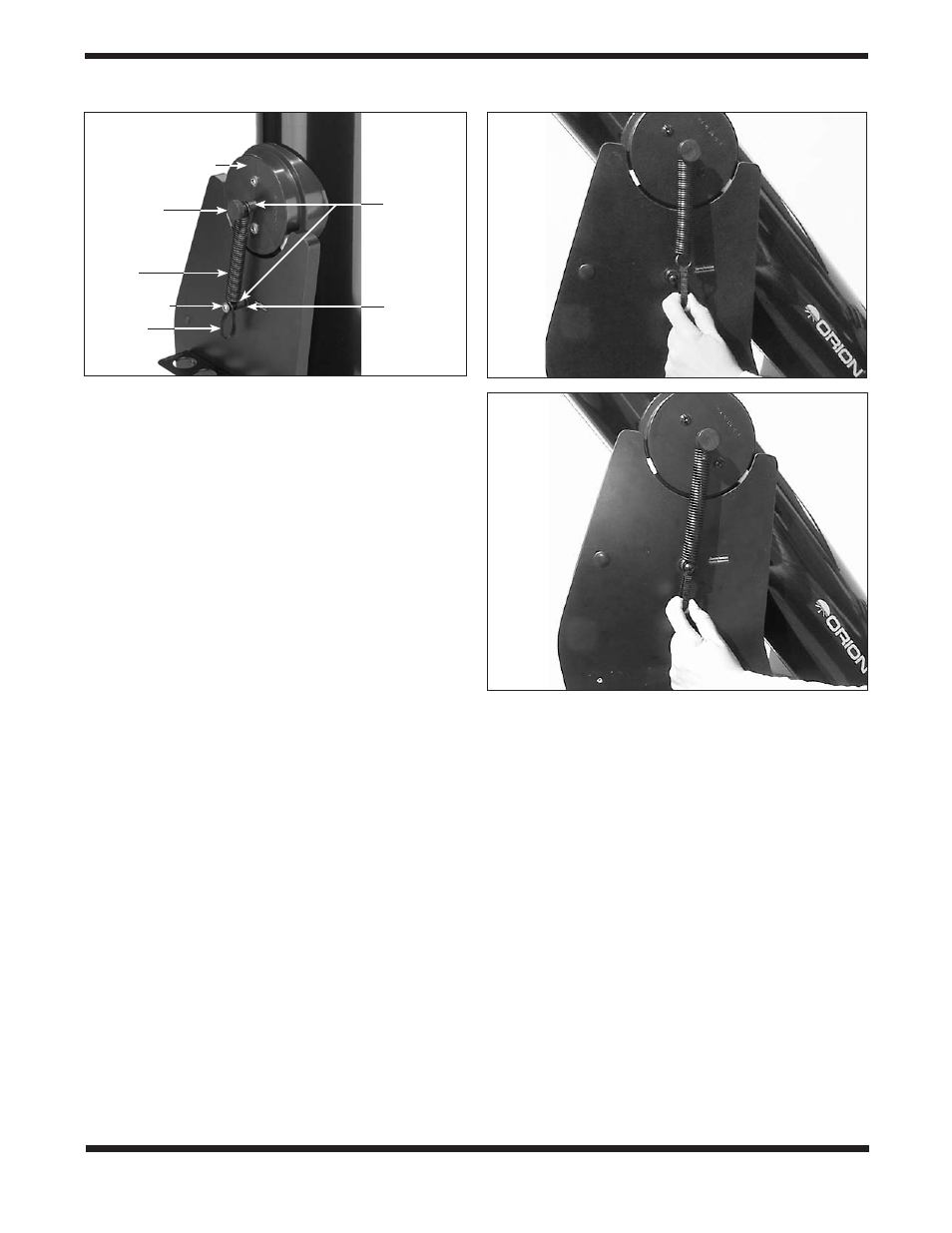
Figure 8.
(a) To attach the spring to the base, grip the pull loop
with your index finger and pull down on the spring.
(b) While pulling
down, slip the end ring of the spring over the bolt head and onto the
narrow part of the nylon spacer, then release the pull loop.
a.
b.
Figure 7.
Close-up view of the CorrecTension system, which pulls
the tube assembly down onto the altitude bearing pads.
Black nylon
spacers
1/4" washer
(black)
Altitude side bearing
Screw with
round knob
Spring
Phillips-head
screw (black)
Pull loop