Specifications – Omega Vehicle Security LVCN700 Series User Manual
Page 2
Step One
SPECIFICATIONS
Range:
LVCN704: 2" to 4'
(5 cm to 1.2m)
LVCN709: 4" to 9.8'
(10 cm to 3m)
LVCN716: 4" to 16.4'
(10 cm to 5m)
LVCN126: 8" to 26.2'
(20 cm to 8m)
Repeatability:
0.25" (6 mm)
Adjustability:
Over entire range
Hysteresis:
LVCN704/709: 0.5" (1.2 cm)
(single set point)
LVCN716/726: 1" (2.5 cm)
(single set point)
Beam width:
LVCN704/709: 2" (5 cm) dia.
LVCN716/726: 3" (7.6 cm) dia.
Dead band:
LVCN704: 2" (5 cm)
LVCN709/716: 4" (10 cm)
LVCN726: 8" (20 cm)
LED indication:
Power, relay and echo status
Calibration:
Target, push button
Memory:
Non-volatile
Supply voltage:
AC: 95-250 VAC
DC: 12-28 VDC (Optional)
Consumption:
AC: 20 watts max.
DC: 100 mA @ 24 VDC (Optional)
Contact type:
(3) SPDT relays
Contact rating:
60 VA
Contact logic:
Single point: alarm
Two point: latching or
out of bounds alarms
Duplex or Alternation:
(Relays 1 and 2 only)
Contact fail-safety:
De-energizes during echo signal loss
Process temp.:
F: -4° to 140°
C: -20° to 60°
Temp. comp.:
Automatic
Electronics temp.:
F: -40° to 160°
C: -40° to 71°
Pressure:
30 psi (2 bar) @ 25° C., derated @
1.667 psi (.113 bar) per °C. above
25° C.
Enclosure rating:
NEMA 4X (IP65)
Enclosure vent:
Water tight membrane
Encl. material:
PC/ABS FR
Trans. material:
PVDF Kynar®
Process mount:
LVCN704/709: 1" NPT (1" G)
LVCN716/726: 2" NPT (2" G)
Mount. gasket:
Viton®
Conduit entrance:
Dual, 1/2" NPT
Classification:
General purpose
CE compliance:
EN 61326 EMC
[DC series only (DC powered)]
Handling Static-Sensitive Circuits/Devices:
When han-
dling the Ultrasonic switch, the technician should follow
these guidelines to reduce any possible electrostatic charge
build-up on the technicians body and the electronic part.
1. Always touch a known good ground source before handling the
part. This should be repeated while handling the part and more
frequently after sitting down from a standing position, sliding
across the seat or walking a distance.
2. Avoid touching electrical terminals of the part unless making connections.
3. DO NOT open the unit cover until it is time to calibrate.
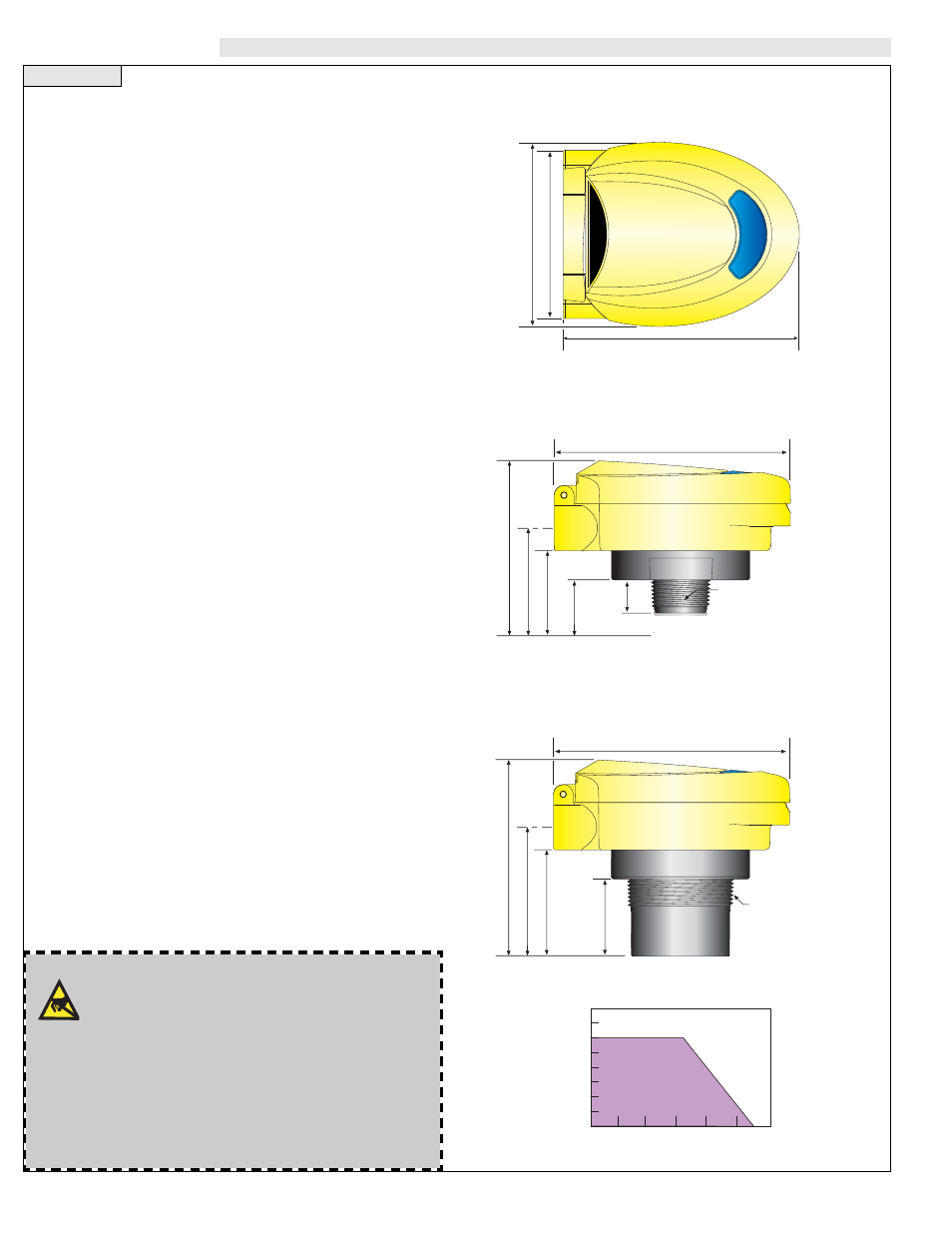
1.2"
(32 mm)
1.9"
(49 mm)
3.9"
(100 mm)
5.2"
(133 mm)
2.4"
(62 mm)
1" NPT
(1" G)
0.75"
(19 mm)
LU75
LU72
2.5"
(63 mm)
4.5"
(1
14 mm)
5.2"
(133 mm)
3.0"
(76 mm)
2" NPT
(2" G)
1.7"
(44 mm)
4.1"
(104 mm)
5.2"
(133 mm)
3.8"
(96 mm)
40
30
20
10
00
-40
-20
00
20
40
60
80
Acceptable
Range
Unacceptable
Range
Temperature/Pressure Derating
Operating Pressure (psi)
Temperature (C¡)
LVCN716
LVCN726
Enclosure (Side View)
LVCN704
LVCN709
Enclosure (Side View)
LVCN700 Series
Enclosure (Top View)