3-3. connecting microcontroller to usb controller – Oki JOB60851 User Manual
Page 53
Chapter 4 Software Development
page 4-18
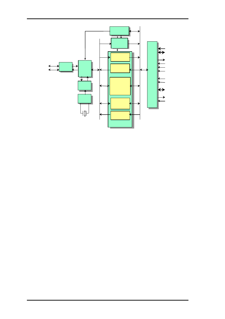
Figure 4.3.1. ML60851C Block Diagram
Protocol engine operation for a control transfer setup transaction differs from that for all other
transactions.
Setup transactions always write the eight bytes in the associated data packet to the setup registers. If
this data is received successfully, the protocol engine sends an ACK back to the host. It also sends a
setup interrupt to the control microcontroller to request register readout.
Data receive transactions write the data from the USB bus to the specified endpoint's receive buffer
if there is room. If this data is received successfully, the protocol engine sends an ACK back to the
host. It also sends a data received interrupt for the command to the control microcontroller. If there
is no room in the receive buffer or there is an error, the protocol engine sends an NAK back to the
host.
Data transmit transactions send a data packet from the specified endpoint's transmit buffer to the
USB bus if there one ready. If the host then sends an ACK completing the transaction, the Data
transmit transactions send a data packet from the specified endpoint's transmit buffer to the USB bus
if there one ready. If the host then sends an ACK completing the transaction, the protocol engine
empties the buffer. It also sends a transmit buffer empty interrupt to the control microcontroller to
request more data.
4-3-3.
Connecting Microcontroller to USB Controller
The ML60851C offers the following configuration options for the microcontroller interface.
(1) Choice, with ADSEL pin, of separate or multiplexed address and data buses
(2) Choice, with register setting under program control, of 8- or 16-bit DMA
The 16-bit data bus is only available when 16-bit DMA is used.
The JOB60851 board uses separate address and data buses, an 8-bit data bus, and no DMA.
Transceiver
/receiver
D+
Protocol
engine
DPLL
D-
EP0 receive
buffer ( 8 bytes)
Status and
control registers
Setup
registers
(8 bytes)
EP0 trasmit
buffer (8bytes)
EP1 receive/
trasmit double
buffer
(64 bytes x 2)
EP2 receive/
transmit buffer
(64 bytes)
Microcontroller
-DMA
interface
A7-A0
D15-D8
RD/
WR/
CS/
INTR/
FIFO
USB
EP3 transmit
buffer (8 bytes)
AD7- AD0
ALE
Oscillator
DACK
DREQ
ADSEL