Chapter 3 system specifications, Page 3-9 – Oki JOB60851 User Manual
Page 31
Chapter 3 System Specifications
page 3-9
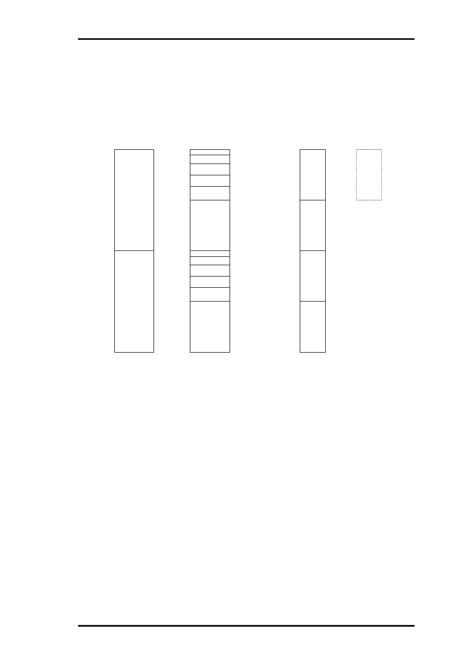
(2) Flash execution mode
This mode maps the code memory to the Flash memory and the data memory to work RAM. It
executes the program in Flash memory. Cutting the power does not erase the program, which
starts automatically when the power is next applied.
Figure 3.2.5. Memory Map for Flash Execution Mode
1:0000h
0:0200h
0:1200h
0:0000h
SFR/XSFR
Int._RAM
0:8000h
0:3000h
0:2000h
Ext._SRAM(A)or(B)
ML60851A
1:0200h
1:1200h
1:8000h
1:3000h
1:2000h
1:FFFFh
Data Memory
0:0000h
Program Memory
SFR/XSFR
Int._RAM
ML60851A
Loader Mode2 memory map
( Load_Sel/ = L ) ( EA/ = H )
Int._FlashROM
(Loader Program)
1:0000h
0:0000h
0:8000h
1:8000h
1:FFFFh
Ext._SRAM
0:0000h
Ext._EPROM
0:7FFFh
(A)
(B)
(C)
(D)
(E)
Ext._SRAM(A)or(B)
Ext._SRAM(A)or(B)
Ext._SRAM(C)or(D)
Ext._SRAM(C)or(D)
Ext._SRAM(C)or(D)
1:0000h
1:FFFFh
Int._FlashROM
(Only M66Q577)