The status register, The a/d software trigger register, 4 the status register – Omega 1002 User Manual
Page 31: 5 the a/d software trigger register
3.2.2.4 The Status Register
Address 10h is used is the status register. Reading from this address will
return the data from the status register. The format of status register is:
Bit7-6 Bit5 Bit4 Bit3 Bit2 Bit1 Bit0
Gain
Control
8245
Timer 1
8245
Timer 0
8245
Timer 2
Reserved
Analog
input type
A/D Busy
Bit 7-6: Current A/D gain control.
Bit 5 : Output of 8254 timer 1.
Bit 4 : Output of 8254 timer 0.
Bit 3 : Output of 8254 timer 2.
Bit 2 : Reserved. Used for hardware testing.
Bit 1 : Analog input type, ‘1’ indicated that analog input type is single-
ended and ‘0’ indicated analog input is differential.
Bit 0 : A/D busy signal. ‘0’ indicates busy, A/D is under conversion. ‘1’
indicates not busy, A/D is complete conversion and is idle now.
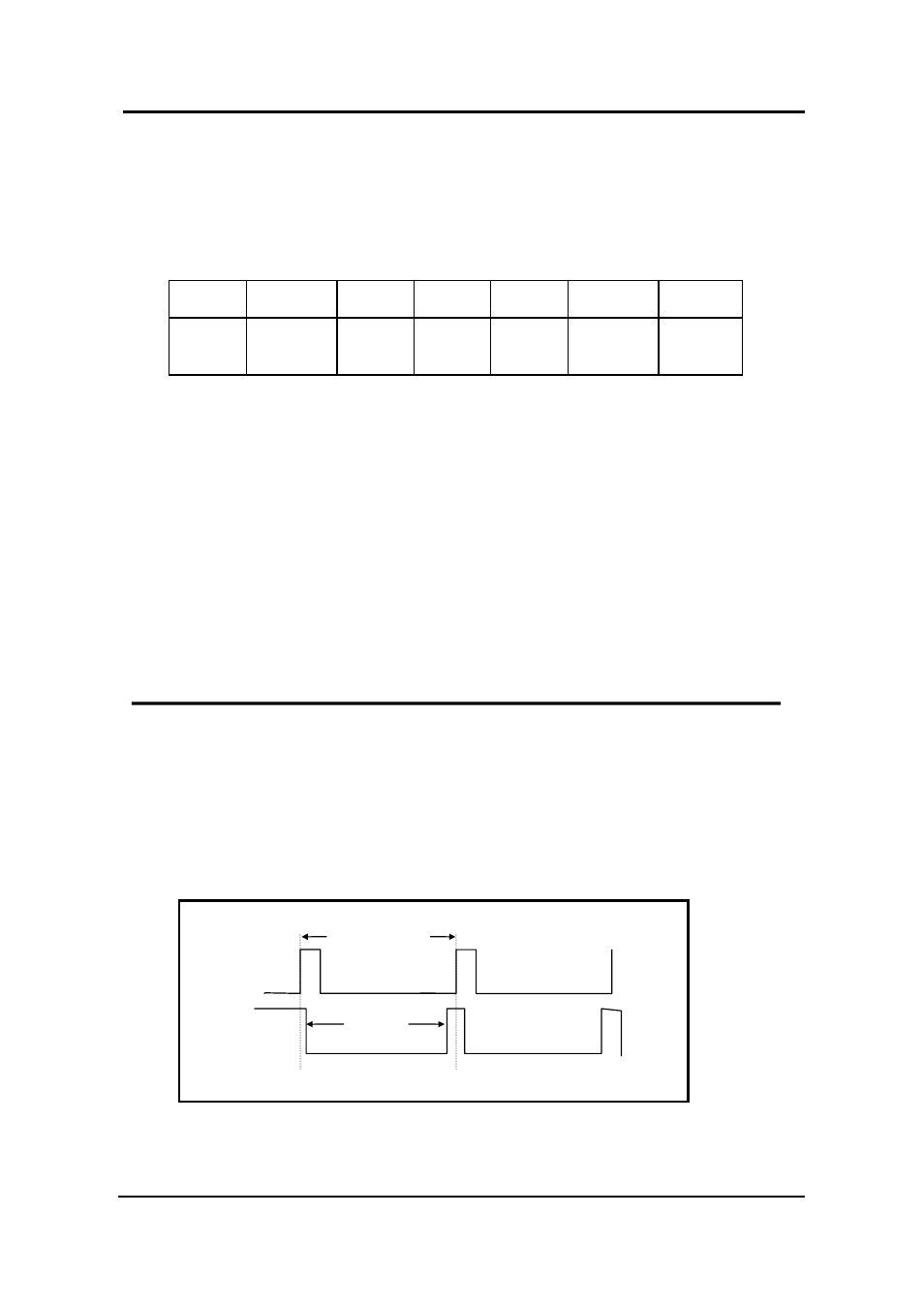
3.2.2.5 The A/D Software Trigger Register
Writing to port 1Ch will generate an A/D trigger signal.
Note: Since the user can trigger at a rate greater than the speed of A/D converter
(125K), a delay time may be required between successive software triggers
A/D
Busy
Software
trigger
8
µs
Delay time
Conversion Time
Figure 3-1. Software triggered delay time.
31