Rhino Mounts BOOM ARM MOWER DB150 User Manual
Db150, Operator’s manual
© 2011 Alamo Group Inc.
DB150
Published 07/11
Part No. 02964566C
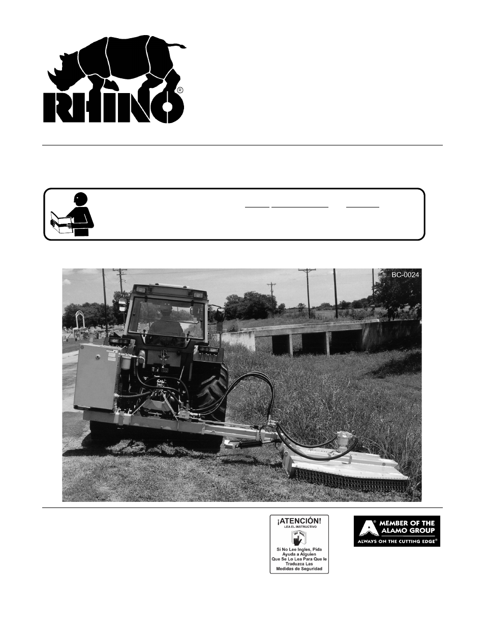
OPERATOR’S MANUAL
RHINO
®
1020 S. Sangamon Ave.
Gibson City, IL 60936
800-446-5158
Email: [email protected]
BOOM ARM MOWER
This Operator's Manual is an integral part of the safe operation of this machine and must
be maintained with the unit at all times. READ, UNDERSTAND, and FOLLOW the Safety
and Operation Instructions contained in this manual before operating the equipment. C01-
Cover
$0.00
Table of contents
Document Outline
- DB150
- OPERATOR’S MANUAL
- RHINO®
- To the Owner/Operator/Dealer
- DEALER to CUSTOMER Pre-Delivery / Operation Instructions
- ROTARY MOWER
- TABLE OF CONTENTS
- GENERAL SAFETY INSTRUCTIONS AND PRACTICES
- OPERATOR SAFETY
- CRUSHING HAZARDS
- CONNECTING OR DISCONNECTING IMPLEMENT SAFETY
- THROWN OBJECTS HAZARDS
- RUN OVER HAZARDS
- PTO ENTANGLEMENT HAZARDS
- MOWER BLADE CONTACT HAZARDS
- HIGH PRESSURE OIL LEAK HAZARD
- ELECTRICAL & FIRE HAZARDS
- TRANSPORTING HAZARDS
- HAZARDS WITH MAINTENANCE OF IMPLEMENT
- PARTS INFORMATION
- Decal Location
- Decal Description
- Federal Laws and Regulations
- Features
- 1. LIMITED WARRANTIES
- 1.01. Rhino warrants for one year from the purchase date to the original non-commercial, governmental, or municipal purchaser (“Purchaser”) and warrants for six months to the original commercial or industrial purchaser (“Purchaser”) that the ...
- 1.02. Manufacturer will replace for the Purchaser any part or parts found, upon examination at one of its factories, to be defective under normal use and service due to defects in material or workmanship.
- 1.03. This limited warranty does not apply to any part of the goods which has been subjected to improper or abnormal use, negligence, alteration, modification, or accident, damaged due to lack of maintenance or use of wrong fuel, oil, or lubricants, ...
- 1.04. Except as provided herein, no employee, agent, Dealer, or other person is authorized to give any warranties of any nature on behalf of Manufacturer.
- 2. REMEDIES AND PROCEDURES.
- 2.01. This limited warranty is not effective unless the Purchaser returns the Registration and Warranty Form to Manufacturer within 30 days of purchase.
- 2.02. Purchaser claims must be made in writing to the Authorized Dealer (“Dealer”) from whom Purchaser purchased the goods or an approved Authorized Dealer (“Dealer”) within 30 days after Purchaser learns of the facts on which the claim is based
- 2.03. Purchaser is responsible for returning the goods in question to the Dealer.
- 2.04. If after examining the goods and/or parts in question, Manufacturer finds them to be defective under normal use and service due to defects in material or workmanship, Manufacturer will:
- 2.05. Purchaser is responsible for any labor charges exceeding a reasonable amount as determined by Manufacturer and for returning the goods to the Dealer, whether or not the claim is approved. Purchaser is responsible for the transportation cost for...
- 3. LIMITATION OF LIABILITY.
- 3.01. MANUFACTURER DISCLAIMS ANY EXPRESS (EXCEPT AS SET FORTH HEREIN) AND IMPLIED WARRANTIES WITH RESPECT TO THE GOODS INCLUDING, BUT NOT LIMITED TO, MERCHANTABILITY AND FITNESS FOR A PARTICULAR PURPOSE.
- 3.02. MANUFACTURER MAKES NO WARRANTY AS TO THE DESIGN, CAPABILITY, CAPACITY, OR SUITABILITY FOR USE OF THE GOODS.
- 3.03. EXCEPT AS PROVIDED HEREIN, MANUFACTURER SHALL HAVE NO LIABILITY OR RESPONSIBILITY TO PURCHASER OR ANY OTHER PERSON OR ENTITY WITH RESPECT TO ANY LIABILITY, LOSS, OR DAMAGE CAUSED OR ALLEGED TO BE CAUSED DIRECTLY OR INDIRECTLY BY THE GOODS INCLU...
- 3.04. NO ACTION ARISING OUT OF ANY CLAIMED BREACH OF THIS WARRANTY OR TRANSACTIONS UNDER THIS WARRANTY MAY BE BROUGHT MORE THAN TWO (2) YEARS AFTER THE CAUSE OF ACTION HAS OCCURRED.
- 4. MISCELLANEOUS.
- 4.01. Proper Venue for any lawsuits arising from or related to this limited warranty shall be only in Guadalupe County, Texas.
- 4.02. Manufacturer may waive compliance with any of the terms of this limited warranty, but no waiver of any terms shall be deemed to be a waiver of any other term.
- 4.03. If any provision of this limited warranty shall violate any applicable law and is held to be unenforceable, then the invalidity of such provision shall not invalidate any other provisions herein.
- 4.04. Applicable law may provide rights and benefits to purchaser in addition to those provided herein.
- General Assembly
- 1. Prepare the area where the unit is to be assembled. The area should be on a hard concrete floor that has been swept clean of all dust and contaminants. Un-package the mower unit carefully so that the seals on the hydraulic components are not broke...
- 2. Inspect and clean all hydraulic hoses and fittings prior to installing them onto the tractor or mower. If dirt or material is seen in any of the parts, they should be washed and cleaned thoroughly with an oil-compatible solution. Do not blow the m...
- TRACTOR PREPARATION
- HEAD ATTACHMENT
- ATTACHMENT OF HYDRAULIC HOSES
- SIDE GAUGE WHEEL (OPTIONAL)
- 1. OPERATOR REQUIREMENTS
- 3. GETTING ON AND OFF THE TRACTOR
- 4. STARTING THE TRACTOR
- 5. CONNECTING THE MOWER TO THE TRACTOR
- 5.1 Connecting the Boom Mower
- 1. Make sure the tractor is equipped with the correct PTO shaft. Change shafts if needed.
- 2. Shorten or remove the tractor drawbar to avoid interference when raising and lowering the boom mower.
- 3. Board the tractor and start the engine. Position the tractor to the boom mower with the 3-point lift arms positioned between the respective set of A-frame lift lugs. NOTE: Set the 3-point lift control to “Position Control” so that the lift arm...
- 4. Turn off the tractor engine and dismount.
- 5. One lift arm at a time, align arm end hole between the set of A-frame lift lugs. Insert hitch pin through the lug and arm holes and insert retaining pin into hitch pin.
- 6. Walk around to opposite side and repeat procedure for remaining lift arm and hitch pin.
- 7. Extend or retract 3-point top link to align its end hole with the holes of the mower’s top link. Insert the top link hitch pin and insert retaining pin into hitch pin.
- 8. Adjust any lower link check chains, guide blocks, or sway blocks to prevent the mower from swaying side to side and possible contact with tractor rear tires.
- 5.1 Connecting the Boom Mower
- 6. SETTING THE MOWER
- 7. DRIVELINE ATTACHMENT
- 8. PRE-OPERATION INSPECTION AND SERVICE
- 9. DRIVING THE TRACTOR AND IMPLEMENT
- 10. OPERATING THE BOOM UNIT AND ATTACHED HEAD
- 11. DISCONNECTING THE MOWER FROM THE TRACTOR
- 12. TRANSPORTING THE TRACTOR AND IMPLEMENT
- HAZARDS WITH MAINTENANCE OF IMPLEMENT
- PARTS INFORMATION
- Proper Oil Level
- DRIVELINE LUBRICATION
- MAIN DRIVELINE & CAT 4 SAFETY SHIELD
- BLADES
- BLADE SERVICING
- BLADE SHARPENING
- BLADE CARRIER REMOVAL
- Boom Cylinder Removal and Replacement Instructions
- 1. Clear the area of all personnel before lowering the boom mower head.
- 2. From the tractor seat with your seat belt fastened around you, Lower the boom mower head to the ground. Extend the boom to the furthest reach and lower the mower head flat on the ground. DO NOT attempt to replace the cylinders with the boom in the...
- 3. Shut off the tractor, engage the parking brake, place the tractor transmission in the park position, and remove the key before dismounting.
- 4. Allow the system to cool to room temperature before removing any hydraulic components.
- 5. Wear Safety glasses and impenetrable gloves when working with hydraulic hoses and fittings.
- 6. Release all oil pressure from the hydraulic circuit by manually stroking each valve section with the tractor engine off. Utilize the Manual Override function if the unit is equipped with an electric over hydraulic valve.
- 7. Utilize blocks, jack stands or a suitable over head hoist to support the weight of the boom section and remove pressure form the cylinder mounting pins.
- 8. Check to see that the cylinder to be replaced is not under pressure by moving the cylinder pins by hand. The pins should be loose and should slide form the pin bore easily. If the pins are tight and cannot be moved, the cylinder may be under press...
- 9. Cylinder assemblies are heavy and can fall when the pins are removed. Support the hydraulic cylinder with a suitable hoist or jack.
- 10. Slowly loosen the hydraulic connections to the cylinder. Carefully unscrew hose fitting and allow any remaining pressure to bleed off. Use Extreme Care. Oil must be cool, and the technician should stand to the side to prevent exposure to any hydr...
- 11. Cap both ends of the fitting with suitably sized metal caps.
- 12. Remove the cylinder pins starting with the ROD end cylinder pin. Make sure the cylinder is properly supported, and remove the base end cylinder pin. The cylinder may be heavy, use proper lifting techniques to lift and handle the cylinder. If need...
- 13. Measure the distance between the cylinder pin holes and extend the new cylinder the correct length prior to attempting an installation.
- 14. Install the new cylinder in place and install both cylinder pins and retaining hardware.
- 15. Remove the metal caps, and re-install the hydraulic hoses.
- 16. Check the hydraulic reservoir of the boom mower to ensure there is sufficient oil. Follow the manufactures recommendations for proper oil type and filtering techniques and requirements to add oil to the system.
- 17. Clear the area of all persons prior to starting the tractor.
- 18. Consult the Operator's Manual for instruction in regard to the proper operating procedure.
- 19. From the tractor seat, with the seat belt fastened, operate the boom to ensure proper operation of the boom function.
- 20. From the tractor seat, with the seat belt fastened, operate the boom controls to fully extend and retract the new cylinder several times to purge any trapped air from the system.
- 21. From the tractor seat, with the seat belt fastened, look for signs of and oil leak. If an oil leak is observed, shut the tractor down and follow the steps to remove pressure from the hydraulic circuit. Identify the source of the leak, and resolve...
- 22. Upon completion of the required repairs, return to Step # 16 to recheck the cylinder for proper operation.
- Hydraulic Component Maintenance Schedule
- STORAGE
- SERVICE OF SPINDLE HOUSING
- MOTOR & COUPLING INSTALLATION
- TAPER BUSHING & SHEAVE INSTALLATION
- START UP PROCEDURE
- 1. Read all safety instructions. Decals on the Machete Boom warn you of particular and multiple hazards. Many decals are attached close to part of the Machete Boom where there is a possible hazard. Read and make sure you understand the safety message...
- 2. Before operating, read all the safety and operating instructions in the Operators Manual for both the tractor and mower.
- 3. When the hydraulic tank has been filled and the mower unit properly assembled, the unit should be started up. NOTE: Make sure that no materials, tools, or jacks, have been left under the mower head. Make sure the front and rear of the mower are pr...
- 4. Start the tractor and idle at a slow engine speed until oil is being pumped.
- 5. Engage the Cutter Control Valve at low engine PTO Speed and run the mower slowly for a short period until all air is removed from the hoses. Keep all persons WELL CLEAR of mower since Blades can THROW OBJECTS with great velocity for a considerable...
- 6. With the area clear of any ground and overhead obstructions, work each cylinder on the boom one at a time, several times, to expel any air in the Hoses and Cylinders.
- 7. Run the Mower Head for 5 minutes. While the tractor is idling, blocked, wearing protective clothing and eye protection, CAREFULLY check for leaking hydraulic fittings, hoses and ports at this point with a piece of cardboard. DO NOT USE YOUR HAND! ...
- 8. Check the fluid level in the Hydraulic Tank on the Tractor, and add oil if required. As the air has been forced out of the Cylinders and Hoses, it goes into the Hydraulic Tank and reduces the oil level. Check your Tractors Operators Manual for the...
- MAINTENANCE SECTION
- Front Cover Number.pdf
- DB150
- OPERATOR’S MANUAL
- To the Owner/Operator/Dealer
- DEALER to CUSTOMER Pre-Delivery / Operation Instructions
- Front Cover SP Number.pdf
- DB150
- MANUAL DE OPERADOR
- Al propietario/operador/distribuidor
- Instrucciones de operaciones antes de la entrega del DISTRIBUIDOR al CLIENTE
- LUBRICACIÓN E HIDRÁULICA
- CORTADORA
- ACCESORIOS E INSTALACIÓN
- CONEXIONES DE CORTADORA A TRACTOR
- ELEMENTOS DE SEGURIDAD
- Complete Ind Ag Mower Eng-Span Online10-10.pdf
- English Cover.pdf
- Page 1
- Complete Ind Ag Mower Spanish 10-10.pdf
- Spanish Cover.pdf
- Page 1
- Spanish Cover.pdf
- Complete Ind Ag Mower Spanish 10-10.pdf
- Spanish Cover.pdf
- Page 1
- Spanish Cover.pdf
- English Cover.pdf