Rhino Mounts RHD88 User Manual
Operator’s manual, Super heavy duty flail mower
©2011 Alamo Group Inc.
$0.00
Published 02/11
Part No. 803215C
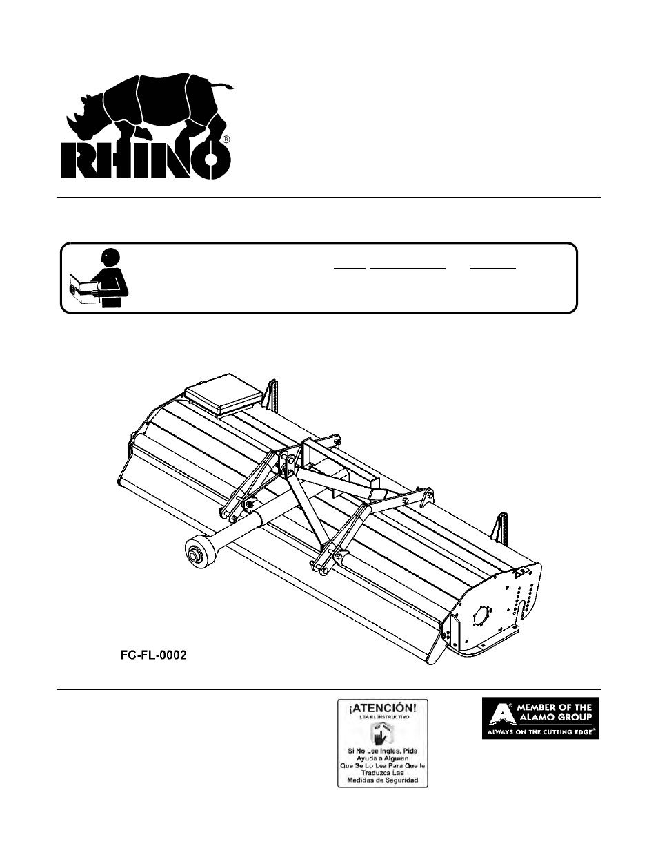
OPERATOR’S MANUAL
RHINO
®
1020 S. Sangamon Ave.
Gibson City, IL 60936
800-446-5158
E-mail: [email protected]
Super Heavy Duty
Flail Mower
This Operator's Manual is an integral part of the safe operation of this machine and must
be maintained with the unit at all times. READ, UNDERSTAND, and FOLLOW the Safety
and Operation Instructions contained in this manual before operating the equipment. C01-
Cover
RHD62, RHD74
RHD88, RHD96
Table of contents
Document Outline
- RHD62, RHD74
- RHD88, RHD96
- OPERATOR’S MANUAL
- To the Owner/Operator/Dealer
- Alamo Group Ag. Division is willing to provide
- one (1) AEM Mower Safety Practices Video
- Table of Contents
- Operator Safety Instructions and Practices
- Transporting Safety Instructions and Practices
- Decal Location
- Rhino RHD62, RHD74, RHD88 & RHD96 SUPER-HEAVY-DUTY FLAIL MOWER OPERATION INSTRUCTIONS
- 1. Standard Equipment and Specifications
- 2. OPERATOR REQUIREMENTS
- 3. Tractor Requirements
- 4. GETTING ON AND OFF THE TRACTOR
- 5. STARTING THE TRACTOR
- 6. CONNECTING THE MOWER TO THE TRACTOR
- 6.1 Connecting the Mower A-Frame to the Tractor
- 1. Make sure the tractor is equipped with the correct PTO shaft. Change shafts if needed.
- 2. Shorten or remove the tractor drawbar to avoid interference when raising and lowering the mower.
- 3. Board the tractor and start the engine. Position the tractor to the mower with the 3-point lift arms positioned between the respective set of mower A-frame lift lugs. Note: Set the 3-point lift control to “Position Control” so that the lift ar...
- 4. Turn off the tractor engine and dismount.
- 5. One lift arm at a time, align arm end hole between the set of A-frame lift lugs. Insert hitch pin through the lug and arm holes and insert retaining pin into hitch pin.
- 6. Walk around to opposite side and repeat procedure for remaining lift arm and hitch pin.
- 7. Extend or retract 3-point top link to align its end hole with the holes of the mower’s top link. Insert the top link hitch pin and insert retaining pin into hitch pin.
- 8. Adjust any lower link check chains, guide blocks, or sway blocks to prevent the mower from swaying side to side and possible contact with tractor rear tires.
- 6.1 Connecting the Mower A-Frame to the Tractor
- 7. SETTING THE MOWER
- 7.1 Roller Height Adjustment
- 1. Place the tractor and mower on a level surface and completely lower the mower to the ground.
- 2. Shut down the tractor, place the transmission in park, and set the parking brake before dismounting.
- 3. One section at a time, place lifting device (scissors jack or hydraulic jack) under center of cutter housing.
- 4. Remove hex nuts, washers and carriage bolts from bracket at each end of roller. Make certain that roller bracket is free to move once the fasteners are removed. A stuck roller could drop unexpectedly and cause injury.
- 5. Use lifting device to reposition cutter housing to desired cutting height. Align bracket holes with cutter housing, then reinstall hardware.
- 6. Lower cutter housing to the ground and remove lifting device.
- 7. Set cutting height according to procedures above for remaining two cutter sections. Make sure that all three rollers are set at the same height to ensure a even cut across the entire width of the mower.
- 7.1 Roller Height Adjustment
- 8. DRIVELINE ATTACHMENT
- 9. PRE-OPERATION INSPECTION AND SERVICE
- 10. DRIVING THE TRACTOR AND IMPLEMENT
- 11. OPERATING THE TRACTOR AND IMPLEMENT
- 12. DISCONNECTING THE MOWER FROM THE TRACTOR
- 13. MOWER STORAGE
- 14. TRANSPORTING THE TRACTOR AND IMPLEMENT
- 15. TROUBLESHOOTING GUIDE
- Problem Possible Cause Remedy
- Check for missing knives on Replace missing knives
- cutter shaft.
- Check to see if knives are Free knives so they swing.
- free swinging.
- Blade broken or bent. Replace blades.
- Cuttershaft bent. Replace cuttershaft.
- Drivelines not phased correctly. Replace driveline.
- Implement & Tractor yokes must
- be in line.
- Cuttershaft bearing worn Replace bearings
- Improper type lubricant. Replace with proper lubricant.
- Excessive trash build-up Remove trash.
- around gearbox.
- Bearing or gears set up Consult your Dealer.
- improperly.
- Worn Bearing. Replace bearing.
- (Rubbing on pulleys or belt).
- Worn Bearing or Gear. Replace Bearing or Gear.
- Bent shaft. Replace oil seal and shaft.
- Shaft rough in oil seal area. Replace or repair shaft.
- Oil seal installed wrong. Replace seal.
- Oil seal not sealing in the housing. Replace seal or use a sealant on
- OD of Seal.
- Oil level too high. Drain oil to proper level.
- Sand hole is casting. Replace castings or gearbox.
- Gasket damaged. Replace gasket.
- Bolts loose. Tighten bolts.
- Clutch Slips Excessively Clutch linings badly worn or Repair clutch per maintenance
- plates warped. section of manuals.
- Too much power for clutch. Reduce ground speed and material
- intake.
- Oil on facings. Replace facings.
- Friction facings glazed. Clean with emery cloth.
- Cutting in rocky conditions. Increase cutting height.
- Soft “will fit” knives. Use genuine Rhino knives.
- Blades dull. Check blades for sharpness.
- Grass too wet. Wait for grass to dry.
- Grass too long. Mow at 3-1/2” and recut lower.
- Travel speed too fast. Use a lower tractor gear.
- PTO RPM too low. Mow at engine RPM to match 540
- PTO RPM.
- Rough, uneven ground. Use a slower speed.
- Lower rollers.
- Turning Tractor too fast. Slow down when turning.
- Mower deck not level. Level the mowing deck.
- Blades dull or unbalanced. Sharpen or balance blades.
- Deck underside plugged. Clean underside of deck.
- Grass too high. Mow at 3-1/2” and recut lower.
- Housing plugged. Clean underside of deck.
- Spring broke & belt off idler. Replace spring or adjust belt.
- Housing plugged. Clean underside of housing.
- Debris around pulleys. Remove deck belt shield and clean
- out debris.
- Grass too high. Mow at 3-1/2” and recut lower.
- OPERATION SECTION
- MAINTENANCE SECTION
- Maintenance Instructions
- Problem Possible Cause Remedy
- 1. Standard Equipment and Specifications
- Lubrication
- Banjo Gearbox
- Driveline Shield
- Slip Clutch
- Seasonal Clutch Maintenance
- 1. It is important that the clutch lining plates slip when an obstacle or load heavier than the clutch setting is encountered. Therefore, if the machine sits outside longer than 30 days and is exposed to rain and/or humid air it is important to make ...
- 2. Loosen nuts (Figure Mnt-FL-0003) on springs until the springs can freely rotate, yet remain secure on bolts.
- 3. Attach mower to tractor and start the tractor. Set the engine speed at 1200 RPM.
- 4. Mark outer plates as shown in Figure Mnt-FL-0003.
- 5. Engage the PTO (approximately one second) and then quickly disengage it. The friction lining plates should break loose (check the mark).
- 6. Turn tractor off and tighten the nuts on the springs to their original position of 1-5/16” compressed spring length.
- To Disassemble Universal Joint
- 1. Remove all snap rings.
- 2. Position joint in loose vice, strike top arm of unsupported yoke to drive the top cup up. Repeat on opposite side.
- 3. If you cannot grip the loosened cap per Step 4, use a pointed tool to tip a needle them repeat Step 2.
- 4. Grip loosened cup in vise, strike yoke arm to drive yoke off cup. Repeat on opposite cup.
- 5. Support cross in loose vise and strike yoke arm. Repeat Step 4 to remove remaining two cups.
- 1. Smear grease into bearings and check for dirt.
- 2. Insert cup and cross. Drive in with spacer.
- 3. Insert snap ring
- 4. Insert second cup and hold cross into cup. Drive cup flush with arm.
- 5. Drive cup down with spacer and insert snap ring
- 6. To loosen cross, strike yoke arm and check cross for free rotation
- 7. Position second yoke on cross. Repeat Steps 2 to 6.
- 8. Grease Kit after assembly is completed.
- Seasonal Clutch Maintenance
- Replacing Cutter Unit Drive Belt
- 1. Place unit on ground or support securely.
- 2. Remove belt guard.
- 3. Remove idler arm spring.
- 4. Remove extension shaft housing mounting bracket front bolt and loosen rear bolt.
- 5. Loosen extension shaft housing mounting bracket rear bolt.
- 6. Pivot extension shaft housing mounting bracket assembly. Remove old belt and install new one.
- 7. Reinstall front mounting bolt then secure extension shaft housing mounting bracket to unit.
- 8. Reinstall idler arm spring and belt guard.
- Setting Cutting Height
- 1. Place the tractor and mower on a level surface and completely lower the mower to the ground.
- 2. Shut down the tractor, place the transmission in park, and set the parking brake before dismounting.
- 3. Place lifting device (scissor jack or hydraulic jack) under center of cutter housing.
- 4. Remove hex nuts, washers and carriage bolts from bracket at each end of roller. Make certain that roller bracket is free to move once the fasteners are removed. A stuck roller could drop unexpectedly and cause injury.
- 5. Use lifting device to reposition cutter housing to desired height. Align bracket holes with cutter housing, then reinstall hardware.
- 6. Lower cutter housing to the ground and remove lifting device.
- Changing Rotation of Cuttershaft
- 1. To reverse direction of cuttershaft rotation, three left hand parts must be ordered: belt guard, outboard bearing plate and an idler pulley arm. A front trash deflector is also required. Refer to the parts section of this manual for part numbers a...
- 2. With the mower housing securely blocked up, remove cuttershaft and turn 180 degrees.
- 3. Remove gearbox cuttershaft drive pulley and outboard bearing plate. Attach new mounting plate to opposite side of mower housing.
- 4. Remove four gearbox bolts and rotate gearbox 180 degrees to new position.
- 5. Install Cuttershaft pulley, gearbox output pulley, idler arm pulley assembly, and belt on housing right side.
- 6. Attach new belt guard.
- 1. Remove skid plate, front cover plate and front shield.
- 2. Loosen powerband belt tensioner and remove powerband belt from gearbox sheave.
- 3. Remove four gearbox bolts and remove gearbox.
- 4. Change positions of gearbox vented plug and drain plug.
- 5. Rotate gearbox 180 degrees and re-mount.
- 6. Replace powerband belt and re-tension.
- 7. Reattach skid plate, front cover plate and front shield.
- Roller Bearing Replacement
- 1. Remove roller and both bearing and bracket assemblies from mower. Lift the mower only high enough to remove the roller assembly.
- 2. Slide bearing and bracket assemblies off each end of roller.
- 3. Remove roller bearing and housing assembly attaching hardware. Remove assembly from bracket. Inspect seal between assembly and bracket for brittleness, cracks, wear and tear. Replace if necessary.
- 4. Remove grease fitting from the top of bearing housing.
- 5. Remove bearing from housing by rotating bearing 90° sideways and line up with notches in bearing housing then pull out.
- 6. Install new bearing into housing. Bearing must be installed with grease hole in bearing aligned with grease fitting hole in housing.
- 7. Reinstall grease fitting to housing. Grease fitting must have locking pin installed which inserts into grease hole in bearing when installed. If grease fitting does not have a pin, order a new grease fitting. Grease fitting must be tight and seate...
- 8. Attach roller bearing and housing assembly to bracket with seal between housing and bracket.
- 9. Slide bearing and bracket assemblies on each end of roller.
- 10. Check bearing for proper installation in housing by gently rocking bearing and bracket assembly in end of roller. Play should be slight to none at all.
- 11. Install roller and bearing and bracket assemblies on mower.
- 12. Lubricate roller bearing until lubricant can be seen coming out between roller and bearing housing.
- Cuttershaft Bearing Replacement
- Cuttershaft Replacement
- General Information on Flail Mower Vibration
- TO THE OWNER/OPERATOR/DEALER
- RHINO
- LIMITED WARRANTY
- 1. LIMITED WARRANTIES
- 1.01. Rhino warrants for one year from the purchase date to the original non-commercial, governmental, or municipal purchaser (“Purchaser”) and warrants for six months to the original commercial or industrial purchaser (“Purchaser”) that the ...
- 1.02. Manufacturer will replace for the Purchaser any part or parts found, upon examination at one of its factories, to be defective under normal use and service due to defects in material or workmanship.
- 1.03. This limited warranty does not apply to any part of the goods which has been subjected to improper or abnormal use, negligence, alteration, modification, or accident, damaged due to lack of maintenance or use of wrong fuel, oil, or lubricants, ...
- 1.04. Except as provided herein, no employee, agent, Dealer, or other person is authorized to give any warranties of any nature on behalf of Manufacturer.
- 2. REMEDIES AND PROCEDURES.
- 2.01. This limited warranty is not effective unless the Purchaser returns the Registration and Warranty Form to Manufacturer within 30 days of purchase.
- 2.02. Purchaser claims must be made in writing to the Authorized Dealer (“Dealer”) from whom Purchaser purchased the goods or an approved Authorized Dealer (“Dealer”) within 30 days after Purchaser learns of the facts on which the claim is based
- 2.03. Purchaser is responsible for returning the goods in question to the Dealer.
- 2.04. If after examining the goods and/or parts in question, Manufacturer finds them to be defective under normal use and service due to defects in material or workmanship, Manufacturer will:
- (a) Repair or replace the defective goods or part(s) or
- (b) Reimburse Purchaser for the cost of the part(s) and reasonable labor charges (as determined by Manufacturer) if Purchaser paid for the repair and/or replacement prior to the final determination of applicability of the warranty by Manufacturer.
- 2.05. Purchaser is responsible for any labor charges exceeding a reasonable amount as determined by Manufacturer and for returning the goods to the Dealer, whether or not the claim is approved. Purchaser is responsible for the transportation cost for...
- 3. LIMITATION OF LIABILITY.
- 3.01. MANUFACTURER DISCLAIMS ANY EXPRESS (EXCEPT AS SET FORTH HEREIN) AND IMPLIED WARRANTIES WITH RESPECT TO THE GOODS INCLUDING, BUT NOT LIMITED TO, MERCHANTABILITY AND FITNESS FOR A PARTICULAR PURPOSE.
- 3.02. MANUFACTURER MAKES NO WARRANTY AS TO THE DESIGN, CAPABILITY, CAPACITY, OR SUITABILITY FOR USE OF THE GOODS.
- 3.03. EXCEPT AS PROVIDED HEREIN, MANUFACTURER SHALL HAVE NO LIABILITY OR RESPONSIBILITY TO PURCHASER OR ANY OTHER PERSON OR ENTITY WITH RESPECT TO ANY LIABILITY, LOSS, OR DAMAGE CAUSED OR ALLEGED TO BE CAUSED DIRECTLY OR INDIRECTLY BY THE GOODS INCLU...
- 3.04. NO ACTION ARISING OUT OF ANY CLAIMED BREACH OF THIS WARRANTY OR TRANSACTIONS UNDER THIS WARRANTY MAY BE BROUGHT MORE THAN TWO (2) YEARS AFTER THE CAUSE OF ACTION HAS OCCURRED.
- 4. MISCELLANEOUS.
- 4.01. Proper Venue for any lawsuits arising from or related to this limited warranty shall be only in Guadalupe County, Texas.
- 4.02. Manufacturer may waive compliance with any of the terms of this limited warranty, but no waiver of any terms shall be deemed to be a waiver of any other term.
- 4.03. If any provision of this limited warranty shall violate any applicable law and is held to be unenforceable, then the invalidity of such provision shall not invalidate any other provisions herein.
- 4.04. Applicable law may provide rights and benefits to purchaser in addition to those provided herein.
- AEM-FEMA Ind-Agri Mower Manual 10-10.pdf
- English Cover.pdf
- Page 1
- Complete Ind Ag Mower Spanish 10-10.pdf
- Spanish Cover.pdf
- Page 1
- Spanish Cover.pdf
- English Cover.pdf