Important – Renesas Emulation Probe M30850T-EPB User Manual
Page 30
( 30 / 76 )
3.3 Using the Oscillator Circuit on the Target System
To operate this product with an oscillator circuit of the target system, input the oscillator output at
50% duty (within the operating range of the evaluation MCU) into pin X
IN
as shown in Figure 3.5.
Pin X
OUT
should be open. Choose "External" in the emulator debugger to use this clock.
Figure 3.5 External oscillator circuit
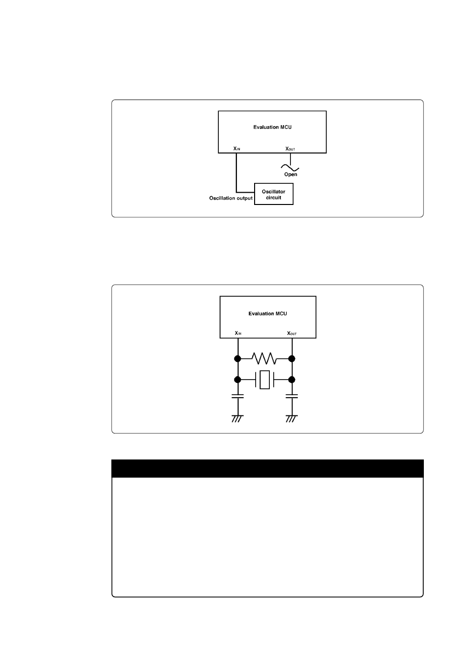
In the oscillator circuit shown in Figure 3.6 where a resonator is connected between pins X
IN
and X
OUT
,
oscillation does not occur because a converter board is used between the evaluation MCU and the
target system.
Figure 3.6 Circuit in which oscillation does not occur (same for X
CIN
and X
COUT
)
IMPORTANT
Notes on External Clock:
• To operate this product with an external clock, construct the oscillator circuit as
shown in Figure 3.5 in the target system and input the oscillator output at 50% duty
(within the operating range of the evaluation MCU) into pin X
IN
. And pin X
OUT
should be open.
• Make note of the fact that in the oscillator circuit shown in Figure 3.6 where a
resonator is connected between pins X
IN
and X
OUT
, oscillation does not occur because
a converter board and other devices are used between the evaluation MCU and the
target system. It is same for sub-clock oscillator circuits (X
CIN
and X
COUT
).