Caution – Renesas Emulation Pod for M30240 Group MCUs M30240T-RPD-E User Manual
Page 26
( 24 / 58 )
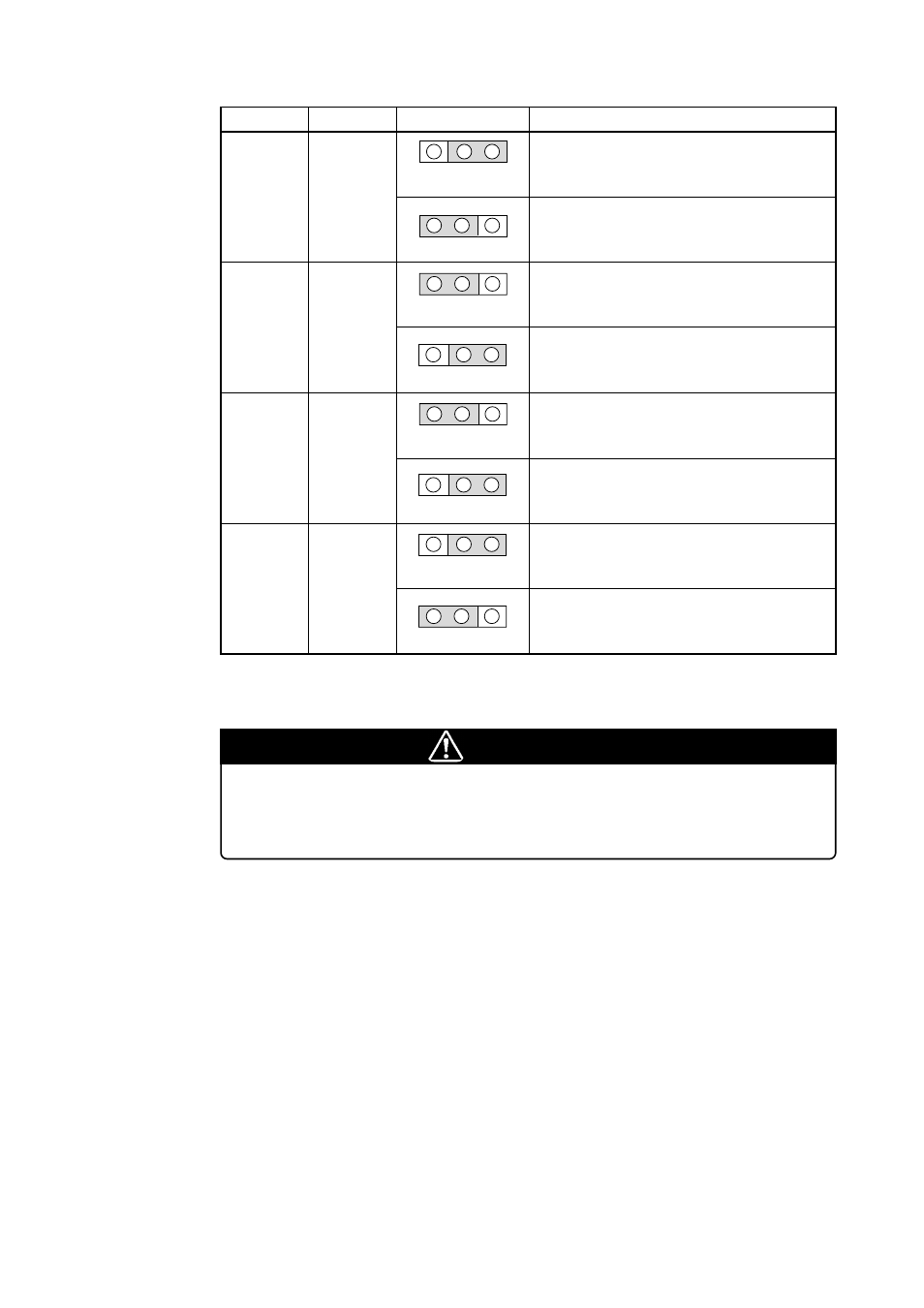
Table 3.1 Switch settings of M30240T-RPD-E
Signal
Switch
Setting
Description
Connects the LPF pin to the LPF circuit in the pod.
JP1
TLPF
BLPF
JP1
TLPF
BLPF
(Factory-setting)
JP2
BXCAP
TXCAP
(Factory-setting)
JP2
BXCAP
TXCAP
JP3
BYPASS
FILTER
(Factory-setting)
JP3
BYPASS
FILTER
JP4
FILTER
BYPASS
JP4
FILTER
BYPASS
(Factory-setting)
LPF
JP1
XCAP
JP2
D+
JP3
D-
JP4
Connects the LPF pin to the target system.
Connects the XCAP pin to the XCAP circuit in the
pod.
Connects the XCAP pin to the target system.
Connects the D+ pin directly to the target system.
Connects the D+ pin to the target system via the
FILTER circuit in the pod.
Connects the D- pin directly to the target system.
Connects the D- pin to the target system via the
FILTER circuit in the pod.
* For the connection diagram of the peripheral circuit of the emulation pod M30240T-RPD-E, refer
to "5.2 Connection Diagram" (page 43).
CAUTION
Note on Changing the Setting of Switches:
• Set the JP3 and JP4 to the same direction (FILTER side or BYPASS side).