Cbl-e1t1/rj45 cable, Fom-e1/t1/r modem card, A.2 fom-e1/t1/r modem card – RAD Data comm T1 User Manual
Page 40
Appendix A Interface Connector Specifications
FOM-E1/T1 Installation and Operation Manual
A-2
FOM-E1/T1/R Modem Card
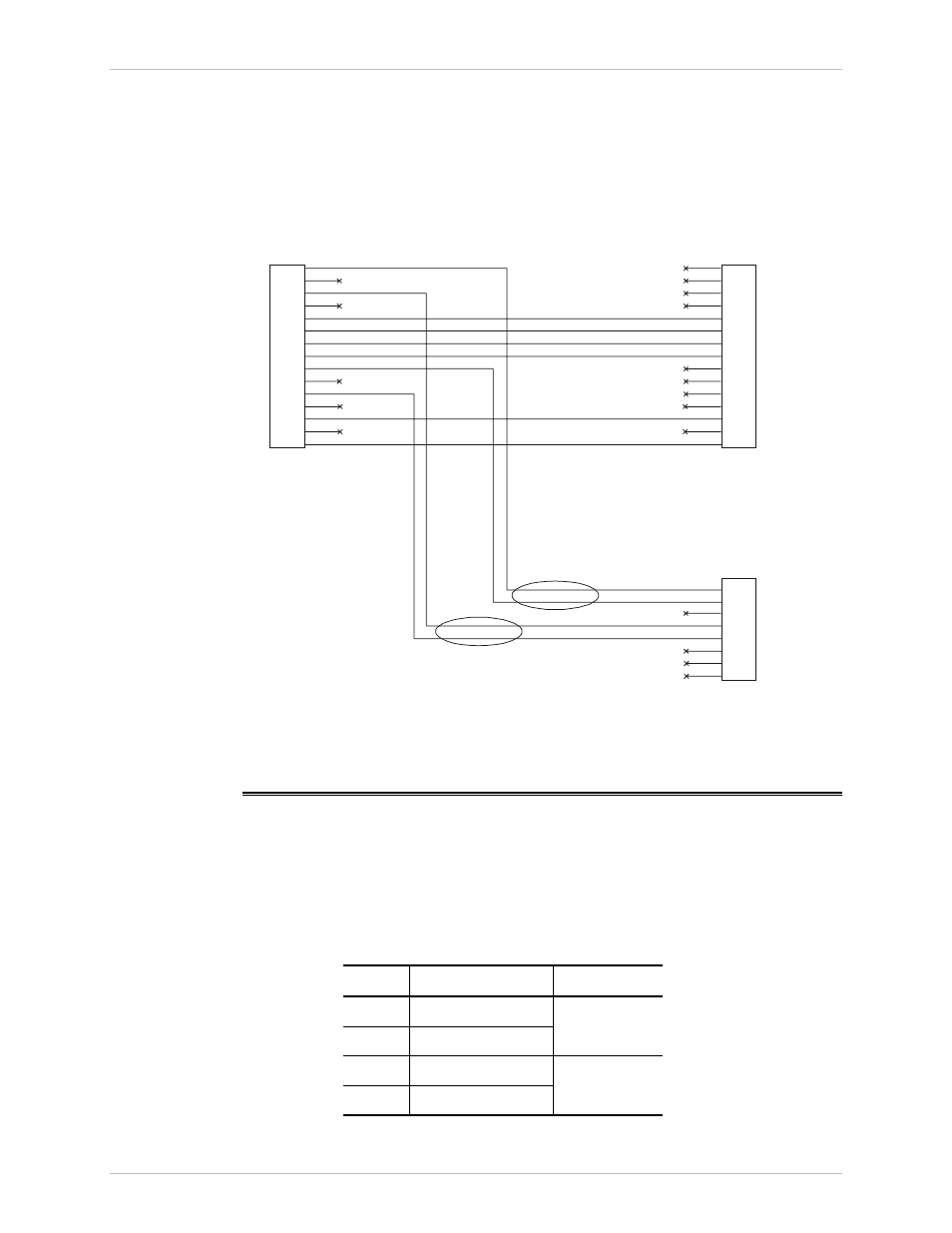
CBL-E1T1/RJ45 Cable
RAD offers an optional splitter cable, CBL-E1T1/RJ45, which connects the DB-15
female connector of the standalone unit to the balanced E1/T1 device and alarm
equipment.
The CBL-E1T1/RJ45 cable includes two DB-15 connectors (male and female) and
one RJ-45 connector.
illustrates the cable schematics.
Male DB-15 Connector
(FOM-E1/T1 Side)
1
RCV (RTIP)
RCV (RTIP)
RCV (RRING)
RCV (RRING)
TRM (TTIP)
TRM (TTIP)
TRM (TRING)
TRM (TRING)
1
1
2
2
2
3
3
3
4
4
4
5
5
5
6
6
6
7
7
7
8
8
8
9
9
10
10
11
11
13
13
14
14
15
15
12
12
Female DB-15 Connector
(Alarm Equipment Side)
Twisted
Twisted
RJ-45 Connector
(E1/T1 Balanced Equipment Side)
Figure A-1. CBL-FOME1T1/RJ45 Scheme
A.2 FOM-E1/T1/R Modem Card
The 25-pin D-type female connector located on the rear panel of the
ASM-MN-214 modem rack serves as an alarm relay port.
lists the
functions of the DB-25 pins.
Table A-3 ASM-MN-214, DB-25 Pin Assignment
Pin Contact
Alarm
Type
10, 22 Normally Closed
10, 21 Normally Open
Minor
13, 25 Normally Closed
13, 24 Normally Open
Major