Chapter 3. operations, Front panel controls and indicators, Hapter 3 – RAD Data comm T1 User Manual
Page 27: Chapter 3 operations, 1 front panel controls and indicators
Front Panel Controls and Indicators
3-1
Chapter 3
Operations
This chapter provides the following information for the FOM-E1/T1 standalone
modem:
• FOM-E1/T1 front-panel indicators and controls
• Operating procedures (turn-on, front-panel indications, performance
monitoring and turn-off).
• Installation procedures given in
must be completed and checked
before attempting to operate FOM-E1/T1.
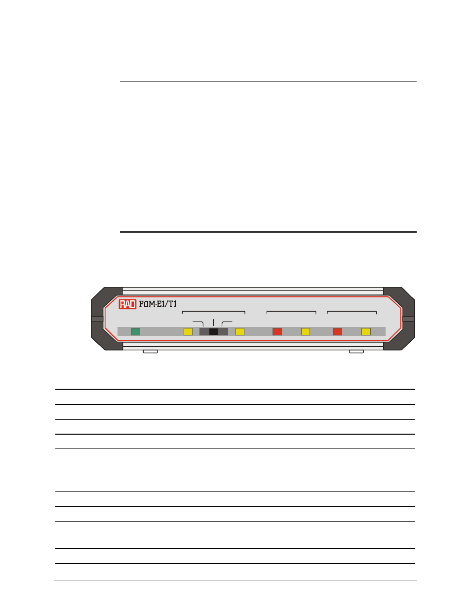
3.1 Front Panel Controls and Indicators
shows the FOM-E1/T1 front panel.
lists the FOM-E1/T1
controls and indicators.
PWR
LOC
REM
NORM
LOW
ERR
AIS
AIS
TEST
ELECTRICAL
OPTICAL
PWR
LOC
REM
NORM
LOW
ERR
AIS
AIS
TEST
ELECTRICAL
OPTICAL
Figure 3-1. FOM-E1/T1 Front Panel
Table 3-1. FOM-E1/T1 Front Panel Controls and Indicators
Name Type
Function
PWR
Green LED
ON – FOM-E1/T1 is powered up
LOC
Yellow LED
ON – A local loopback is active
REM
Yellow LED
ON – A remote loopback is active
TEST
Slide switch
LOC – Activates local analog loopback
REM – Activates remote digital loopback
NORM – Normal operation (no loopbacks are active)
ELECTRICAL LOW
Red LED
ON – E1/T1 electrical input is below G.703 level
ELECTRICAL AIS
Yellow LED
ON – E1/T1 electrical interface received "All 1s" string
OPTICAL ERR
Red LED
ON – Bit error rate of the signal received from at the optical
interface is 10
-6
or worse
OPTICAL AIS
Yellow LED
ON – Fiber optic interface received "All 1s" string