Connecting the interfaces, Connecting the fiber optic interface, Below) – RAD Data comm T1 User Manual
Page 24: Table 2-1
Chapter 2 Installation and Setup
FOM-E1/T1 Installation and Operation Manual
2-4
Installation and Setup
Table 2-1 FOM-E1/T1 Internal Jumpers and Switches
Jumper/Switch Function
Possible
Settings
Factory
Setting
SW3, AIS
When a major alarm is
detected, AIS is
transmitted to either the
electrical or optical
interface.
ON – Transmit AIS
OFF – Do not transmit AIS
ON
SW2, INPUT Ground
SW1, OUTPUT Ground
Controls connection of
the BNC shield to the
chassis ground
CONNECTED – BNC shield is
connected to the
chassis ground
(for E1 unbalanced)
FLOATING – BNC shield is
disconnected from the
chassis ground
(for E1/T1 balanced)
FLOATING
JP2, JP4, JP5, JP6, JP7, JP8,
INTERFACE
Selects the E1/T1
electrical interface
100 ohm BAL T1 – T1 100Ω balanced
(DB-15 connector)
120 ohm BAL CEPT – E1 120Ω
balanced
(DB-15
connector)
75 ohm UNBAL CEPT – E1 75Ω
unbalanced
(BNC
connectors)
120 ohm
BAL CEPT
Note:
For
FOM-E1/T1
units with 115 VAC, factory setting is 100Ω BAL T1.
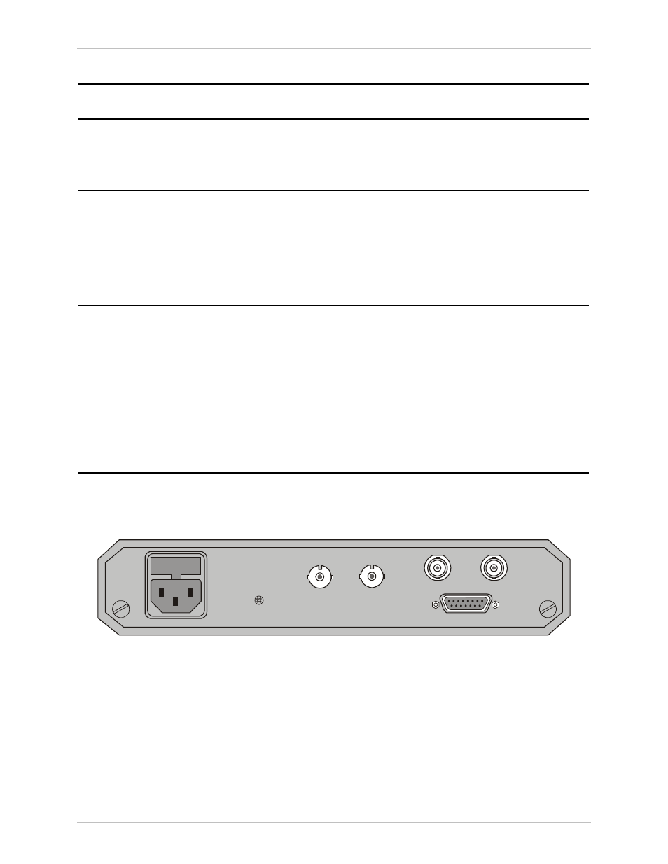
Connecting the Interfaces
illustrates the AC-powered FOM-E1/T1 unit rear panel.
IN
TX
OUT
RX
Figure 2-2 FOM-E1/T1 Rear Panel, AC-Powered Unit
Connecting the Fiber Optic Interface
Two fiber optic ST, SC or FC connectors are located on the rear panel and marked
TX and RX.
To connect the fiber optic cables
1. Remove the protective caps from the connectors and store them in a safe
place for later use.