Rs232/rs485/rs422 plus irig-b via db9, Figure 20: db9 female port pin-out, Table 7: db9 female dte port pin-out with irig-b – RuggedCom RS416 User Manual
Page 26
Serial Ports
26
RuggedCom
®
RuggedServer™ RS416 Family Installation Guide rev118
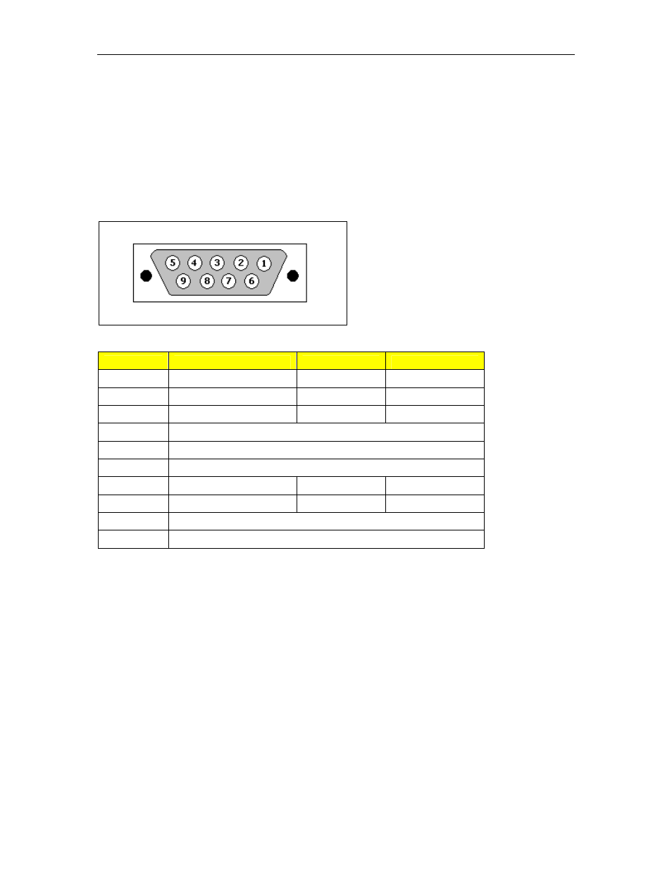
3.3 RS232/RS485/RS422 plus IRIG-B via DB9
Each port is individually selectable via software to be RS232, RS485 or RS422. IRIG-B
signal and ground are available on pins 4 and 6, respectively, for every mode. The DB9
port pin-out diagram and listing are shown below.
NOTE: The RS232 pin configuration of the IRIG-B ports is DTE rather than DCE,
meaning that the port transmits on pin 3 and receives on pin 2. Connection to DTE ports
requires null-modem cabling (pin 2 to 3; pin 3 to 2).
Figure 20: DB9 female port pin-out
Pin
RS232 DTE Mode
RS485 Mode
RS422 Mode
1
-
-
RX-
2
RX
3
TX/RX+
TX+
3
TX
3
-
RX+
4
+IRIG-B
5
Common (Isolated) Ground
6
Common (Isolated) Ground
7
RTS
2
TX/RX-
TX-
8
CTS
2
-
-
9
Common (Isolated Ground)
3
Shield
Chassis Ground
Table 7: DB9 Female DTE Port pin-out with IRIG-B
NOTES:
1. No internal termination is provided.
2. In RS232 mode, pins 7 and 8 are connected internally. These pins enter a high impedance state. A
DCE that asserts RTS will see CTS asserted, although the RuggedServer will not perform hardware
flow control.
3. In RS232 DTE mode, ports receive on pin 2 and transmit on pin 3.
The IRIG-B output on each port is configurable via software to provide IRIG-B pulse-
width modulated output (IRIG-B006 or IRIG-B007) or PPS output, a single pulse per
second on the second.