Esign, Eatures – Rockford Fosgate T1000-4 User Manual
Page 4
4
D
ESIGN
F
EATURES
1
2
3
4
5
67
8
8
9
10 11
11
10
12
12
13
14
15
16
9
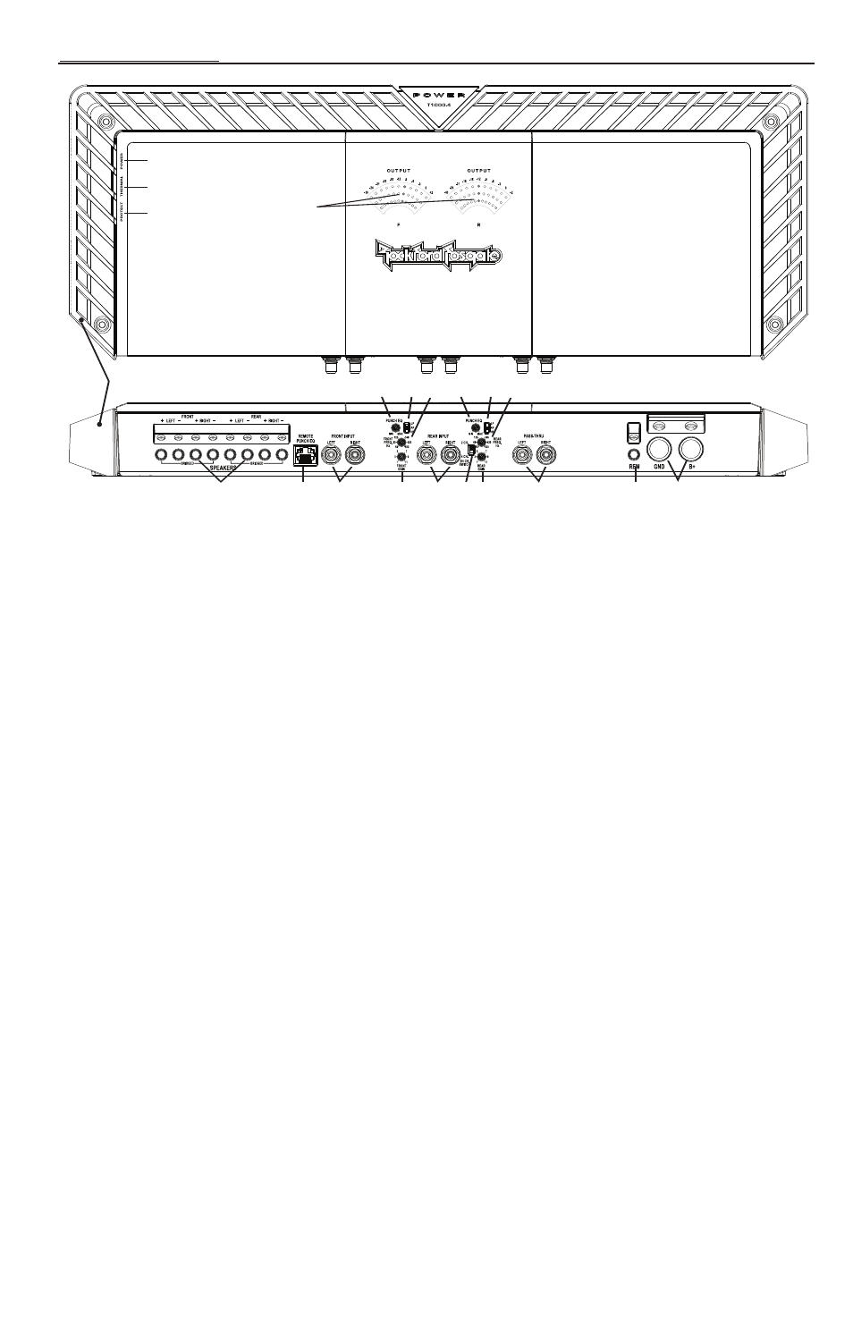
1. Power LED (Top of unit) – This Blue LED illuminates when the unit is turned on.
2. Thermal LED (Top of unit) – This Red LED illuminates if the amplifier’s internal components become
too hot and engage the thermal protection.The amplifier will shut down to cool if this occurs.
3. Protect LED (Top of unit) – This Yellow LED illuminates if a short circuit or too low of an impedance
is detected at the speaker connections.The amplifier will automatically shut down if this occurs.
4. Output Display (Top of unit) – These LEDs simulate VU meters to display the real-time front and
rear output of the amplifier from - 00 (infinity) to +2dB. During normal operation the indicator should
not reach +2dB, as this indicates clipping.
5. Cast Aluminum Heatsink – The cast aluminum heatsink of the Power amplifier dissipates heat
generated by the amplifier's circuitry.
6. Speaker Terminals – The heavy duty, nickel-plated wire connectors (+ and -) will accept wire sizes from
8 AWG to 16 AWG.
7. Remote Punch EQ (Optional Controller) – The Remote Punch EQ connection is made with a RJ-45
cable and can be installed in a variety of ways for easy control access.The control is used to boost low
and/or high frequency information to overcome road noise.The remote overrides the Punch EQ rear
channel control on the amplifier when connected.
NOTE:
Previous (prior to 2007) Punch Bass and Para-Punch remotes will not work with these amplifiers.
8. RCA Input Jacks – These pro-audio panel mount RCA jacks provide an easy connection for signal level
input.They are nickel-plated to resist the signal degradation caused by corrosion.Their design reduces the
stress created to internal boards when RCA cables are connected or disconnected.
9. Punch EQ – A Gyrator based Punch EQ that eliminates frequency shift with boost.This works along
with the crossover switch on the amplifier.When set to Low-Pass (LP) operation, this is a variable Bass
Boost. When set to High-Pass (HP) operation, this is a variable Mid-Bass and Treble Boost. When set to
All Pass (AP) operation, both the Bass and Treble frequencies are boosted.
10. Crossover Switch – Selectable switch for High-Pass (HP),All Pass (AP), or Low-Pass (LP) operation.
11. Variable Crossover – Is a built-in 24dB/octave Butterworth filter with a crossover point variable
from 50Hz to 500Hz.
12. Gain Control – The input gain control is preset to match the output of most source units. It can be
adjusted to match output levels from a variety of source units.
13. 2/4 Channel Switch – Setting this switch to the 2CH. position, switches the inputs to a 2-channel
mode, allowing connection to only the front inputs with a 4-channel output.