Raypak 185A User Manual
Page 12
Page 12
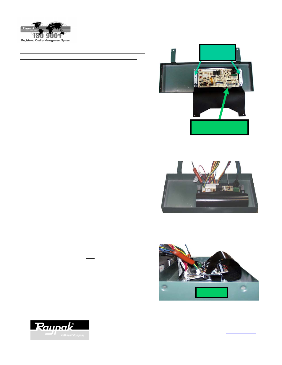
Fig. 33
Fig. 32
CLEAR PLASTIC STRIP
WITH THIN CONNECTOR
Fig. 34
PLASTIC SHIELD & BRACKET INSTALLATION -
MODELS 185, 265, 335 & 405, A & B SERIES:
Make sure the power and gas are off.
1.
Note that the plastic shield is installed under the
front bracket as pictured.
Install the shield brackets and plastic shield using
the existing screws on the control panel as shown
in Fig. 32.
2.
Reconnect the wire harnesses to the board.
(Note the location of the clear plastic strip with the
thin connector. This is sometimes disconnected
when there is a remote control in the system.
Refer to the remote wiring instructions for further
details.)
Note: Make sure 3-wire sensor plug is connected.
3.
Install the plastic shield over the board and attach
to the brackets using the screws and washers
provided in the kit. See Fig. 33 and Fig. 34.
4.
Re-install the sheet metal panel holding the board
back into the heater.
5.
Go to remote operation instructions.
OR
Return the control panel to the upright position
and re-attach using the screws previously
removed.
SIDE VIEW
2151 Eastman Ave., Oxnard, CA 93030 805-278-5300 Fax 800-777-7026
www.raypak.com
Technical support is available M-F, 5:30 AM to 5:00 PM PST, at 800-947-2975 or 800-627-2975
SHIELD
BRACKETS
P/N 241169 Rev.-3