Connectors, Figure 2-2 . cx-70dhd connector locations, 2. cx-70dhd connector locations – Runco CRYSTAL CX-70DHD User Manual
Page 20: Pre l iminar y
6
CX-70DHD Installation/Operation Manual
PRE
L
IMINAR
Y
1.
DISPLAY STAND
Included with the CX-70DHD for table-top installations.
2.
POWER SWITCH
Connects or disconnects the display panel from the AC power source.
3.
STANDBY/ON INDICATOR
- Lights blue to indicate normal operation;
- Lights red to indicate that the CX-70DHD is in standby mode.
4.
REMOTE CONTROL SENSOR
Receives the signals from the remote control.
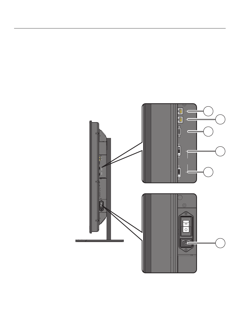
Connectors
Figure 2-2 shows the connector locations on the CX-70DHD, and the paragraphs that
follow describe them.
Figure 2-2. CX-70DHD Connector Locations
➤
IN
OUT
RS-232
IN
ANALOG
IN
OUT
DVI
IN
OUT
RS-232
IN
ANALOG
IN
OUT
DVI
1
2
3
5
4
6