Installation, Vent restrictor position, Inst alla tion – Regency Liberty L900-1 User Manual
Page 13
Regency
®
L900-1 Direct Vent Gas Fireplace
13
INST
ALLA
TION
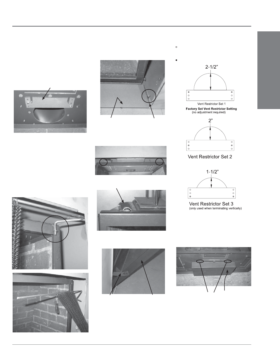
Vent restriction is required for certain venting
installations, see the diagrams in the "Venting
Arrangements" section to determine if they are
required for your installation.
The Vent Restrictor plate is located on the inside
top of the fi rebox.
INSTALLATION
VENT RESTRICTOR POSITION
Screws for plugging the holes.
(all holes must be plugged with a screw).
Screw holes for fi xing the restrictor plate.
Vent Restrictor Plate
To set the vent restriction as indicated in the
venting arrangements diagrams, refer to the
following instructions;
3) Remove the glass door.
a. Release the 2 door latches on the left
and right side at the top of the fi rebox.
b. Swing the door out from the top and release
the hinge on the left side of the door and
lift out.
Latch
Latch Location
4) Remove the screws that hold the vent
restrictor plate in place.
5) Adjust the vent restrictor plate to the required
vent restrictor position as per the diagrams
shown.
6) Once the vent restrictor plate is in the required
position, secure with screws.
Door
Hinge
1) Remove the right side mesh by gathering the
mesh together and lifting the curved end of
the rod up and out of the bracket located on
the top right of the glass frame.
Now slide the straight end of the rod out from
the bracket located on the middle inside top
of the outer shell. Repeat for left side.
Front Cover Plate
Right Side Pin Shown
2) Remove the front cover plate by lifting up
off of the pins on the left and right side of
the fi rebox.
Right Side Rod with Screen Removed
Vent Restrictor Set 4
Baffl e plate
Position the baffl e plate on the top inside
wall of the fi rebox, push it back until it
contacts the back wall of the fi rebox.
When baffl e plate is in position, secure with
2 relief door screws.
7)
Vent Restrictor Set 4 = combination of
Vent Restrictor Set 1 + installation of the
baffl e plate (For application requirements
see vent diagram on page 19).
Relief Door Screws
Loosen the 2 centre relief door screws
(shown below).