Gas supply – Raypak 503-2003 User Manual
Page 19
19
water sample. Water with a high TDS concentration
will greatly accelerate lime and scale formation in the
hot water system. Most high TDS concentrations will
precipitate out of the water when heated. This can
generate a scale accumulation on the heat transfer
surface that will greatly reduce the service life of a
water heater. This scale accumulation can also
impede adequate flow of water and may totally block
the water passages in the tubes of the heat exchang-
er. A heat exchanger that is damaged or blocked by
lime/scale accumulation must be replaced. Failure of a
water heater due to lime scale build up on the heating
surface is non-warrantable. The manufacturer of the
water heater has no control of the water quality, espe-
cially the TDS levels in your system. Total dissolved
solids in excess of 2,500 ppm will accelerate lime and
scale formation in the heat exchanger. Heat exchang-
er failure due to total dissolved solids in excess of
2,500 ppm is a non-warrantable condition. Raypak
offers basic temperature guidelines for operation of a
potable water heater on normal to moderate levels of
hardness and solids but levels of hardness and total
dissolved solids beyond normal limits for operation will
require special setup and operation.
Gas Supply
Gas piping must have a sediment trap ahead of the
heater gas controls, and a manual shut-off valve lo-
cated outside the heater jacket. It is recommended
that a union be installed in the gas supply piping adja-
cent to the heater for servicing. The gas supply
pressure to the heater must not exceed 10.5 in. WC for
natural gas or 13.0 in. WC for propane gas.
A pounds-to-inches regulator must be installed to
reduce the gas supply pressure if it is higher than
noted above. This regulator should be placed a mini-
mum distance of 10 times the pipe diameter upstream
of the heater gas controls. Refer to Table H for maxi-
mum pipe lengths.
Gas Supply Connection
NOTE: Failure of a heat exchanger due to lime
scale build-up on the heating surface, low pH or
other chemical imbalance is non-warrantable.
DANGER: Make sure the gas on which the heater
will operate is the same type as specified on the
heater’s rating plate.
CAUTION: The heater must be disconnected from
the gas supply during any pressure testing of the gas
supply system at test pressures in excess of 1/2 psi
(3.45 kPa).
The heater must be isolated from the gas supply pip-
ing system by closing the upstream manual shut-off
valve during any pressure testing of the gas supply
piping system at test pressures equal to or less than
1/2 psi (3.45 kPa). Relieve test pressure in the gas
supply line prior to re-connecting the heater and its
manual shut-off valve to the gas supply line. FAILURE
TO FOLLOW THIS PROCEDURE MAY DAMAGE
THE GAS VALVE. Over-pressurized gas valves are
not covered by warranty. The heater and its gas con-
nections shall be leak-tested before placing the
appliance in operation. Use soapy water for leak test.
DO NOT use an open flame.
Gas Supply Pressure
A minimum of 4.0 in. WC and a maximum of 10.5 in.
WC upstream gas pressure is required under load and
no-load conditions for natural gas. A minimum of 4.0
in. WC and a maximum of 13.0 in. WC is required for
propane gas. The gas pressure regulator(s) supplied
on the heater is for low-pressure service. If upstream
pressure exceeds these values, an intermediate gas
pressure regulator, of the lockup type, must be
installed.
When connecting additional gas utilization equipment
to the gas piping system, the existing piping must be
checked to determine if it has adequate capacity for
the combined load.
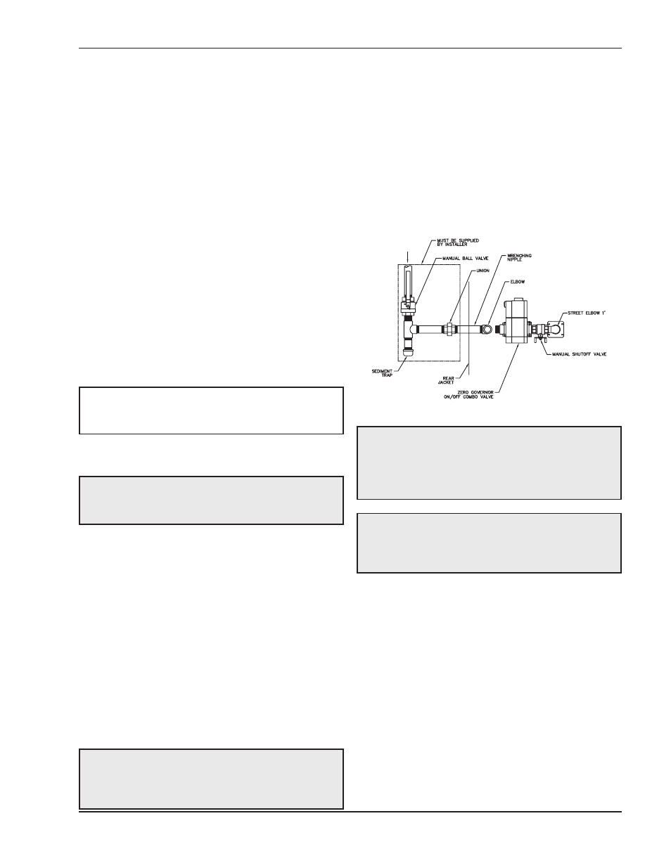
Fig. 15: Gas Supply Connection
CAUTION: Do not use Teflon tape on gas line pipe
thread. A pipe compound rated for use with natural
and propane gases is recommended. Apply
sparingly only on male pipe ends, leaving the two
end threads bare.
CAUTION: Support gas supply piping with
hangers, not by the heater or its accessories. Make
sure the gas piping is protected from physical
damage and freezing, where required.