Raypak 503-2003 User Manual
Page 15
15
Table F: Heater Rates of Flow and Pressure Drops
20°F T
30°F T
40°F T
Min. Flow
Max. Flow
Model
No.
gpm
P (ft)
gpm
P (ft)
gpm
P (ft)
gpm
P (ft)
T
gpm
P (ft)
T
503
44
2.8
29
1.4
N/A
N/A
25
1.1
35
100
11.3
9
753
65
6.4
44
3.1
33
1.9
33
1.9
40
100
13.8
13
1003
87
12.0
58
6.0
43
3.7
43
3.7
40
113
18.6
15
1252
109
20.9
73
10.2
54
6.2
54
6.2
40
113
22.2
19
1503
N/A
N/A
87
16.0
65
9.5
65
9.5
40
113
25.5
23
1753
N/A
N/A
102
22.5
76
13.4
76
13.4
40
113
27.2
27
2003
N/A
N/A
116
32.0
87
18.9
87
18.9
40
116
32.0
30
Notes: Basis for minimum flow is ΔT . Basis for maximum flow is gpm.
equipped with flow control valves or other automatic
means to prevent gravity circulation of the heater
water during the cooling cycle. It is highly recommend-
ed that the piping be insulated.
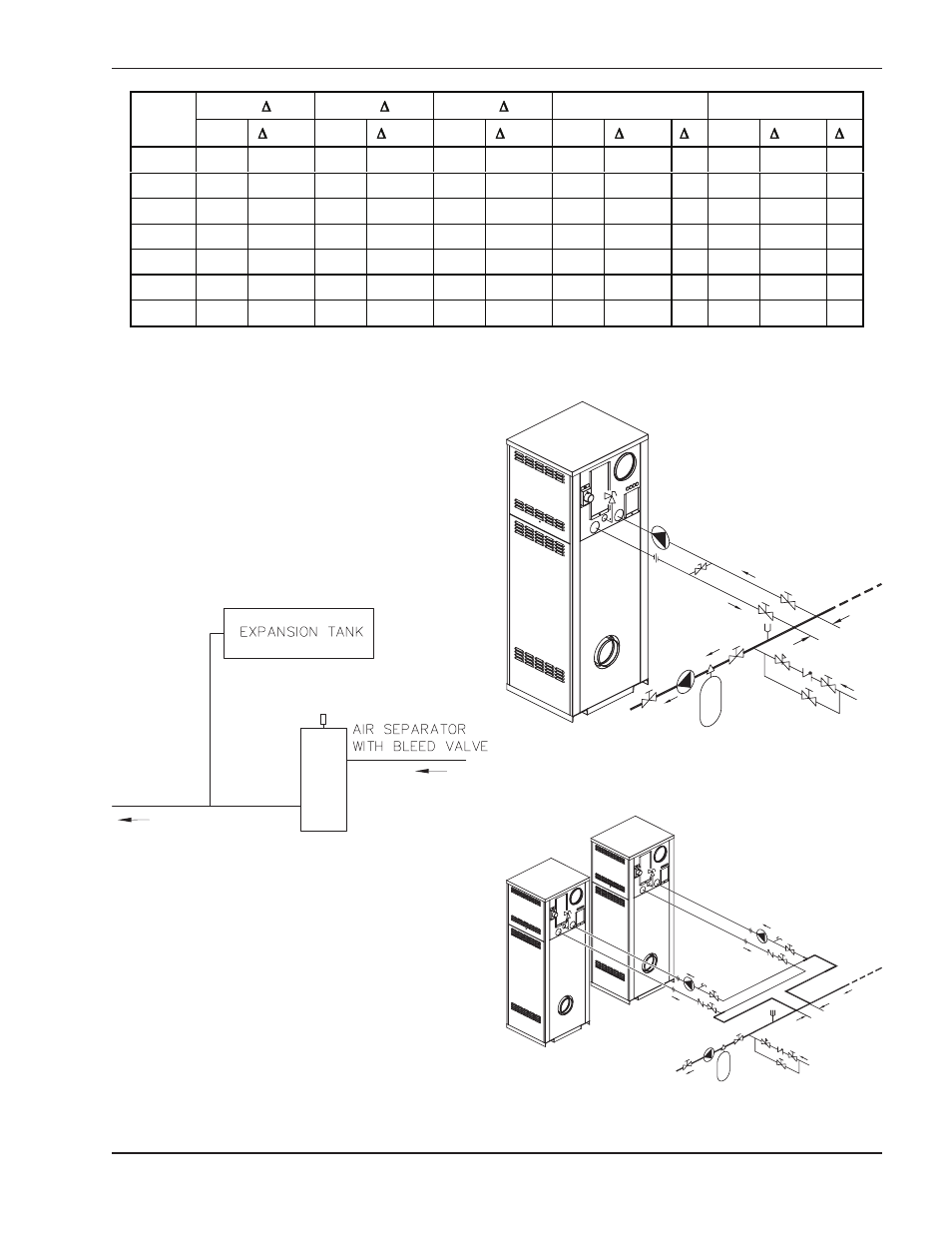
Air-Separation/Expansion Tank
All heaters should be equipped with a properly sized
expansion tank and air separator fitting as shown in
Fig. 9.
Three-Way Valves
Three-way valves intended to regulate system water
temperatures by reducing flow in the boiler should not
be used. Raypak heaters are high-recovery, low-mass
heaters which are not subject to thermal shock. See
Fig. 14 and instructions on page 17 for adjusting the
manual bypass.
Fig. 9: Air-Separation/Expansion Tank
*
Fig. 10: Single Heater - Low-Temperature (Heat Pump)
Application with Primary/Secondary Piping
*
Fig. 11: Dual Heaters (Reverse/Return)
with Primary/Secondary Piping
*Maximum 4 times the pipe diameter or 12”, whichever is less.
*Maximum 4 times the pipe diameter or 12”, whichever is less.