Raypak 135A User Manual
Page 9
9
At the time of removal of an existing heater, the
following steps shall be followed with each appliance
remaining connected to the common venting system
placed in operation, while the other appliances remain-
ing connected to the common venting system are not in
operation.
(a) Seal any unused openings in the common venting
system.
(b) Visually inspect the venting system for proper size
and horizontal pitch and determine there is no
blockage or restriction, leakage, corrosion and
other deficiencies which could cause an unsafe
condition.
(c) Insofar as is practical, close all building doors and
windows and all doors between the space in which
the appliances remaining connected to the com-
mon venting system are located and other spaces
of the building. Turn on clothes dryers and any
appliance not connected to the common venting
system. Turn on any exhaust fans, such as range
hoods and bathroom exhausts, so they will operate
at maximum speed. Do not operate a summer
exhaust fan. Close fireplace dampers.
(d) Place in operation the appliance being inspected.
Follow the lighting instructions. Adjust tankstat
so appliance will operate continuously.
(e) Test for spillage at the draft hood relief opening
after 5 minutes of main burner operation. Use the
flame of a match or candle, or smoke from a
cigarette, cigar or pipe to visually check spillage.
(f) After it has been determined that each appliance
remaining connected to the common venting sys-
tem properly vents when tested as outlined above,
return doors, windows, exhaust fans, fireplace
dampers and any other gas burning appliance to
their previous conditions of use.
(g) Any improper operation of the common venting
system should be corrected so the installation
conforms with the latest edition of the National Fuel
Gas Code, ANSI Z 223.1. When resizing any
portion of the common venting system, the com-
mon venting system should be resized to approach
the minimum size as determined using the
appropriate tables in Chapter 10 and in
Appendix G of the National Fuel Gas Code,
ANSI Z 223.1 and CAN/CGA - B149.1 -B149.2.
GAS SUPPLY CONNECTIONS
The inlet gas connection of the heater gas valve is
1/2". Provide an adequate gas piping supply line no
smaller than 1/2", according to the chart below:
Maximum Equivalent Pipe Length (Feet)
1/2" Pipe 3/4" Pipe 1" Pipe 1-1/4" Pipe
MODEL NAT PROP NAT PROP NAT PROP NAT PROP
0090
30 80 125 300 400 - - -
0135
15 40 60 150 200 500 -
0195
- 20 35 70 100 250 400 -
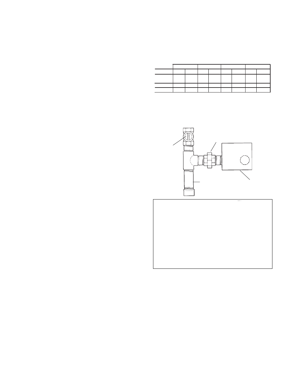
Gas piping must have a sediment trap ahead of the
heater gas controls, and a manual shutoff valve located
outside the jacket. All gas piping should be tested after
installation in accordance with local codes.
CAUTION: The heater and its manual shut off valve must
be disconnected from the gas supply during any pressure
testing of that system at test pressures in excess of 1/
2 psig (3.45 KPA). Dissipate test pressure in the gas
supply line before reconnecting the heater and its manual
shut off valve to gas supply line. FAILURE TO FOLLOW
THIS PROCEDURE MAY DAMAGE THE GAS VALVE.
OVER PRESSURED GAS VALVES ARE NOT COV-
ERED BY WARRANTY. The heater and its gas connec-
tions shall be leak tested before placing the appliance in
operation. Use soapy water for leak test. DO NOT use
open flame.
NOTE: Do not use teflon tape on gas line pipe thread.
A flexible sealant suitable for use with Natural and
Propane gases is recommended.
NOTE: These boilers are also certified to operate on
Propane gas, when equipped with the combination gas
valve and orifices (pilot and main burners) sized for
Propane gas.
GAS PRESSURE-SPECIFICATIONS
Inches W.C.
Regulator
Min.
Max.
Setting
Natural
4.5
10.5
3.5
Propane
12.0 13.0
11.0
Note: Do not exceed maximum inlet gas pressure. The
minimum value shown is for input adjustment.
Sediment Trap Gas Valve
Manual
Union
Valve
Fig. # 8192.0