Raypak 135A User Manual
Page 22
22
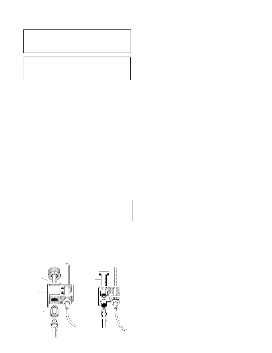
HONEYWELL PILOT ROBERTSHAW PILOT
AIR
OPENING
PILOT
ORIFICE
Fig.# 8045.2
PILOT
Fig.# 8102.1
ORIFICE
ADJUSTMENTS/REPLACEMENTS OF
COMPONENTS
CAUTION: Label all wires prior to disconnection when
servicing controls. Wiring errors can cause improper
and dangerous operation. Verify proper operation after
servicing.
DANGER - SHOCK HAZARD
Make sure electrical power to the heater is disconnect-
ed to avoid potential serious injury or damage to com-
ponents.
1. Gas Valve Replacement
a) Shut off electrical power and gas supply to the
heater.
b) Remove gas piping to gas valve inlet.
c) Disconnect wiring connections, pilot tubing
(when equipped).
d) Remove screws (2) holding the burner tray.
e) Slide burner tray out.
f) Remove gas valve bracket screws and
bracket.
g) Unscrew gas valve from gas pipe.
h) Reverse above procedure to re-install.
2. Pilot Burner Cleaning or Replacement (Standing
Pilot)
a) Shut off electrical power and gas supply to the
heater.
b) Disconnect gas piping to gas valve.
c) Disconnect wiring connections to gas valve.
d) Remove screws (2) holding the burner tray.
e) Slide burner tray out.
f) Remove screw holding pilot lighter tube.
g) Remove screws (2) holding pilot bracket on
the burner tray.
h) Disconnect thermocouple and pilot tubing
from the gas valve.
i)
Remove pilot burner from pilot bracket.
j)
Remove pilot orifice and blow away lint or dirt.
Clean with wire or small brush.
NOTE: Make sure pilot orifice is clear, but do not
enlarge the hole.
k) Reverse above procedure to re-install.
3. Flame Roll-out Switch Replacement
a) Shut off electrical power to the heater.
b) Remove wiring connections to switch.
c) Remove screws (2) holding the switch.
d) Reverse above procedure to re-install.
4. Vent Thermal Switch Replacement
a) Shut off electrical power to the heater.
b) Remove wiring connections to switch.
c) Remove the screws (2).
d) Reverse above procedure to re-install.
5. Ignition Module Replacement
a) Shut off electrical power to the heater.
b) Remove control cover screws and open
control compartment.
c) Disconnect wiring connections to module.
d) Remove screws (2) holding module.
e) Reverse above procedure to re-install.
6. Transformer Replacement
a) Shut off electrical power to the heater.
b) Remove control cover screws and open control
compartment.
c) Disconnect wiring connections from
transformer leads.
d) Remove screws (2) holding transformer.
e) Reverse above procedure to re-install.
7. Circulator Replacement
a) Shut off electrical power to the heater.
b) Shut off water supply and open drain valve
to remove water in the piping at the pump
level.
CAUTION: To avoid damage to electrical components
keep water from getting into the control compartments
and gas valve.
c) Disconnect wiring and conduit connections to
the pump.
d) Remove the nuts and bolts at the inlet and
outlet flanges. Remove old gaskets.
e) Remove the pump.
f)
Reverse the above procedure to re-install.
Use new gaskets and make sure they are
seated properly when tightening the nuts
and bolts.