Raypak 135A User Manual
Page 10
10
The gas valve is provided with pressure taps to measure gas pressure upstream of the gas valve and
downstream which is the same as the manifold pressure.
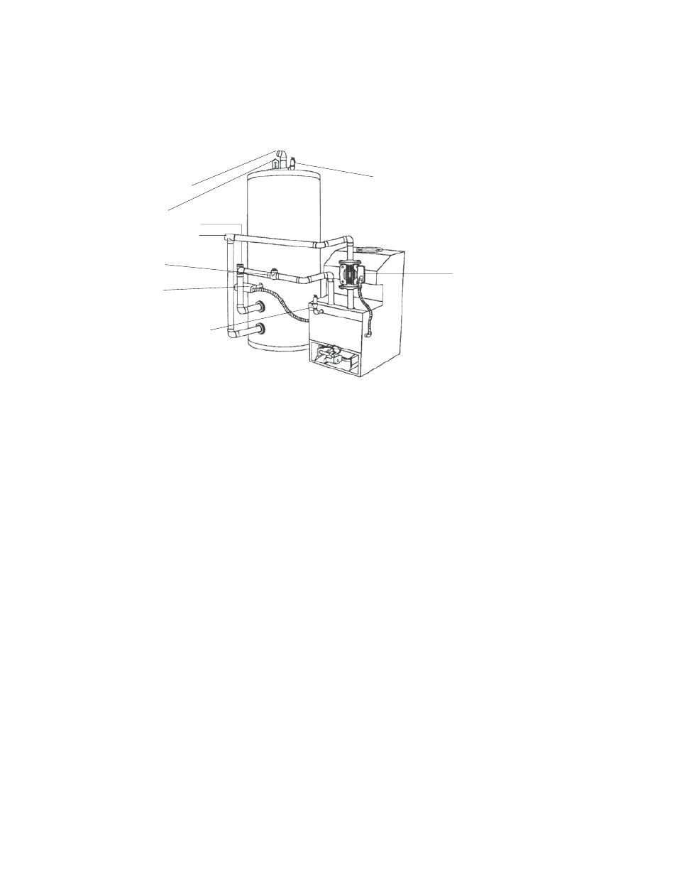
WATER CONNECTIONS & SYSTEM PIPING
The pipe size and fittings between the heater and the tank should be at least 1" for model 90, and
1-1/4" for models 135 and 195. This is based on the tank being located as close to the heater as possible, as shown
in the drawing below:
Hot Water Supply
Thermometer
Cold Water
Recirculation Water
Check Valve
Thermostat
Pressure Relief Valve
T & P Relief Valve
Pump
If this water heater is installed in a closed water supply system, such as one having a back-flow preventer in
the cold water supply line, means shall be provided to control thermal expansion. Contact the water supplier or
local plumbing inspector on how to control this situation.
When this water heater system is supplying general purpose hot water requirements for use by individuals,
a thermostatically controlled mixing valve is recommended to reduce the risk of scald injury. Contact a licensed
plumber or the local plumbing authority for further information.
Thermometer(s) should be installed so that they indicate the water temperature at or near the outlet of the
storage tank.
RELIEF VALVE
A new combination temperature and pressure (T & P) relief valve, complying with the Standard for Relief
Valves and Automatic Gas Shut Off Devices for Hot Water Supply Systems, ANSI Z21.22, must be installed in the
opening provided on top of the storage tank, at the time of installation. No valve is to be placed between the relief
valve and the storage tank.
The pressure rating of the relief valve must not exceed the 160 maximum working pressure indicated on the
water heater rating plate. The BTUH rating of the relief valve must not be less than the BTUH input of the heater.
Connect the outlet of the relief valve to a suitable open drain. The discharge line must pitch downward from
the valve to allow complete draining (by gravity) of the relief valve and discharge line. The discharge line should
be no smaller than the outlet of the valve. The end of the discharge line should not be threaded or concealed, and
should be protected from freezing. No valve of any type, restriction or reducer coupling, should be installed in the
discharge line. Local codes shall govern installation of relief valve.