Chapter 15 description of the interface (e-series), 1 standard interface com a, Fig. 33: com a signal definition and connection – Rackmount Solutions VA 10000 User Manual
Page 48
44
Chloride Active and E-Series UPS User Manual
Chapter 15 Description of the Interface (E-Series)
The E-Series UPS has a standard interface COM A and an optional interface COM B. Protocol data transfer
signal exchange is through COM A RS232 interface or the optional interface (COM B).
These interfaces can be used for:
• Direct communication between UPS and a computer.
• Integration of the UPS as client into a network with centralized monitoring.
• Transfer of operational states to external alarm systems.
The necessary communication software packages and interface cables are available as accessories.
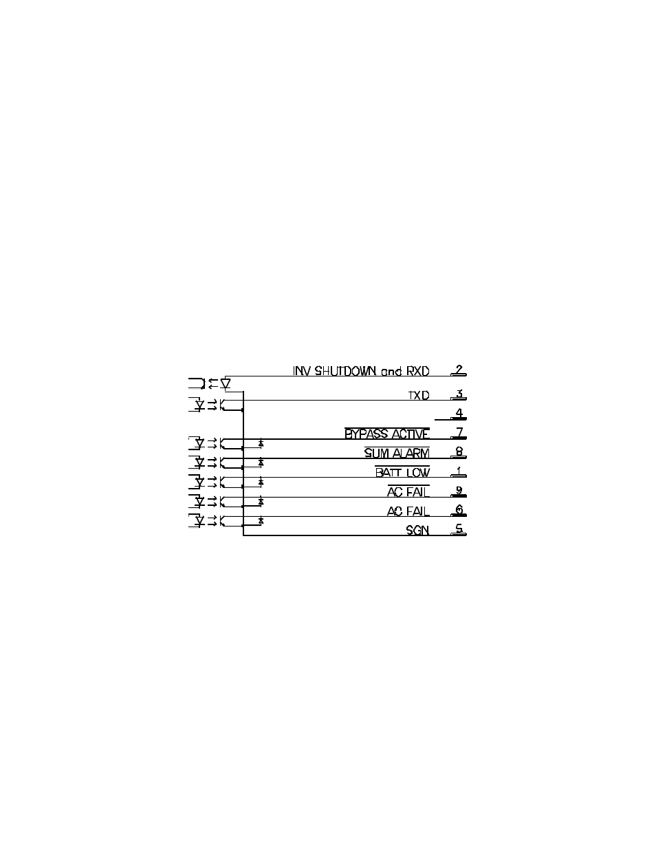
15.1 Standard Interface COM A
The 9-pin SUB-D connector (pin contacts) contains the RS 232 signals, 5 output signals and 1 input signal.
The RS232 signal RXD can also be used as input signal, when the sequential interface is not used.
The 5 alarm outputs are open-collector outputs.
Fig. 33: COM A signal Definition and Connection
The interface COM A is galvanically separated from all other circuits.