4 rudder reference transducer, 5 auxiliary alarm, 6 radio navigation interface – Raymarine PowerPilot User Manual
Page 5: 2 hydraulic drive units, 1 type 0 hydraulic drive, 2 type 1 hydraulic drive
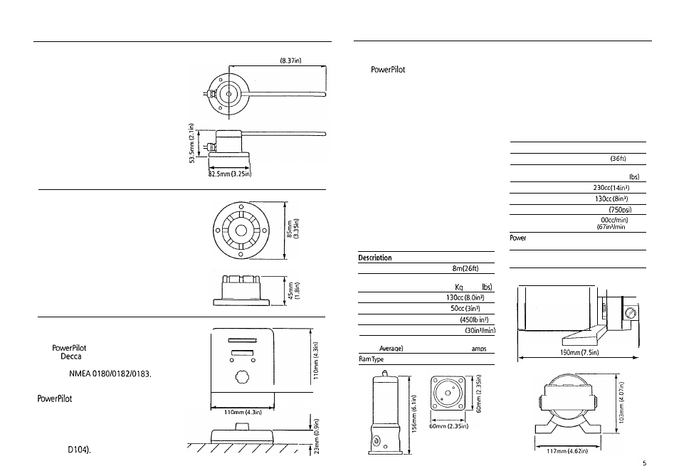
1.1.4 Rudder Reference
Transducer
The rudder reference transducer provides
the course computer with a precise
rudder position. It is mounted on a
suitable base adjacent to the rudder
stock. The interconnecting cable connects
directly to the course computer connector
unit.
213mm
1.1.5 Auxiliary Alarm
(Cat. No. 2035)
The autopilot is provided with an
automatic off course alarm system which
sounds from all control units and provides
sufficient audible warning under most
conditions. In cases where a high power
alarm is necessary, an auxiliary alarm can
be fitted. The auxiliary alarm is connected
to the main connector unit via a two
core cable.
1.1.6 Radio Navigation Interface
(Cat. No. 2057)
The
can be interfaced to any
Loran,
or Satellite Navigation
receiver having a suitable cross track error
output to
The
radio navigation interface computes the
course adjustments to enable the
to steer to a selected waypoint.
The unit is waterproof and designed for
surface mounting (normally adjacent to
the Loran/Satellite Navigation receiver). If
required the unit can be bracket mounted
using the bracket mounting kit
(Cat. No.
1.2 HYDRAULIC DRIVE UNITS
The
is available with one of
two hydraulic drive units, depending on
the size of the vessel and the
displacement of the ram.
The vessel size and displacement
recommendations given below apply to
directly driven steering systems. When a
power steering system is fitted the vessel
size and displacement recommendations
can be ignored.
1.2.1 Type 0 Hydraulic Drive
The type 0 hydraulic drive unit consists of
a twin cylinder piston pump powered by a
small but powerful reversing electric
motor.
The high volumetric efficiency of the
piston pump provides precise control,
with the twin pistons offering smoother
and quieter operation than would be
found with a single cylinder design.
S i z e
Maximum Vessel Size
Maximum Vessel
Displacement
3000
(6600
Maximum Ram Capacity
Minimum Ram Capacity
Regulated Peak Pressure
30 bar
Peak Flow Rate (Unloaded)
490cdmin
Power Consumption
(Typical
1 . 5 - 2 . 5
Double Ended (Balanced)
1.2.2 Type 1 Hydraulic Drive
The hydraulic drive unit consists of a
precision gear pump with integral valve
block driven by a continuously rated servo
motor. The pump drive motor is connected
directly to the course computer which also
regulates peak pump pressure and
eliminates the need for end stroke limit
switches.
Description
S i z e
Maximum Vessel Size
1 lm
Maximum Vessel
Displacement
5500 Kg (12000
Maximum Ram Caoacitv
Minimum Ram Capacity
Reaulated Peak Pressure
50 bar
Peak Flow Rate
(Unloaded)
11
Consumption
(Typical Average)
Ram Type
3.5-6 amps
Single or Double Ended
(unbalanced or balanced)
4