Operation manual guardshield safe 4, Attention – Rockwell Tools GUARDSHIELD SAFE 4 User Manual
Page 15
Operation Manual
GuardShield Safe 4
15
Important information:
Safety devices for connection of GuardShield Safe 4 must
be built with PNP logic. The outputs will be periodically
controlled for short-circuit and cross-fault detection.
The output voltage at the solid-state outputs is
dependant on the power supply and the output load
(see chapter 11 Technical Data).
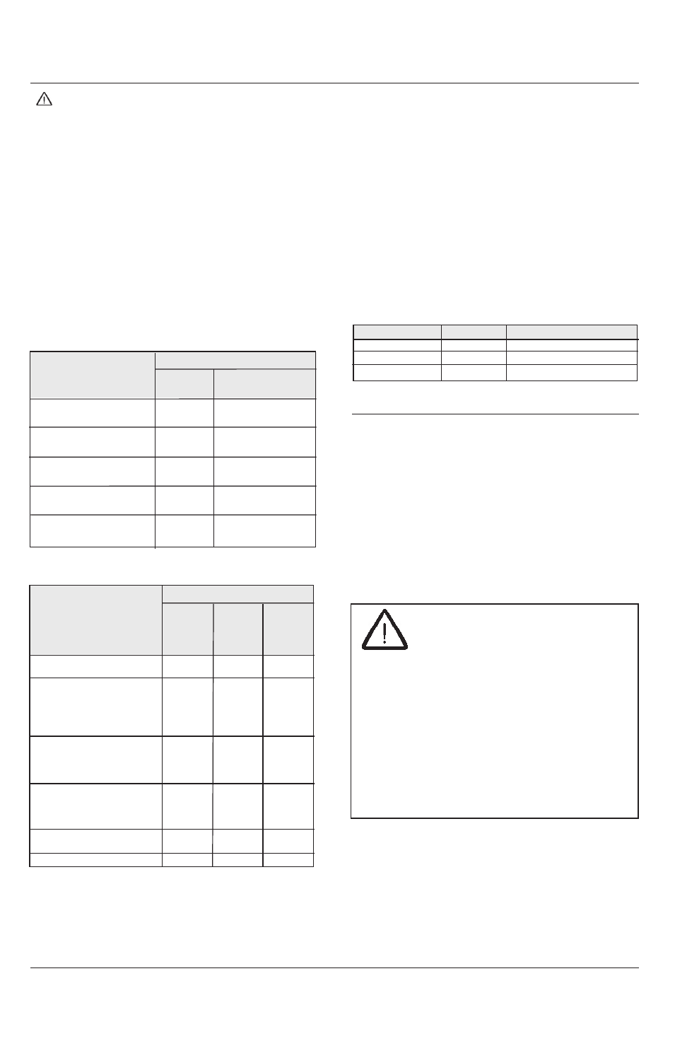
5.3.6. Trouble shooting
Possible errors and operation status are indicated with
the LED indicators on the transmitter and receiver.
Following combinations are relevant:
Table 1: Transmitter
Status
LED
Orange Green
Red
(Power)
(ok)
(Test)
No power supply
off
off
on
(external)
Test input closed
on
on
off
(external)
Test input open
on
off
on
(external)
Controller error
flashing
off
on
(internal)
Protective field error flashing
off
flashing
(internal)
Table 2: Receiver
Status
LED
Orange Green
Red
(Power)
(Protective (Protective
field not
field
interrupted) interrupted)
No power supply
off
off
off
(external)
No sufficient power
on
off
off
(external)
OSSD on (on-load operation,
on
on
off
protective field not interrupted,
normal)
OSSD off (off-load operation,
flashing
off
on
protective field interrupted or
insufficient alignment of the
system)
OSSD error (external, short
all 3s
circuit between OSSD 1 and
short time
off
flashing
OSSD 2, towards 0 V and off
24 VDC)
Controller error (internal)
irregular
off
on
flashing
Protective field error (internal)
flashing
off
flashing
External error: An external interface error can be
resolved by correcting the installation, due to
1.
Receiver: short circuit of both OSSDs, of OSSD
to U
sp
, of OSSD to GND
2.
Transmitter: Test input open
3.
None or too low power supply
4.
Inadequate adjustment of transmitter and
receiver
Internal error (orange LED is irregularly flashing):
Please
contact
the
nearest
ROCKWELL
AUTOMATION representative.
Normal operation
Transmitter
Receiver
Operation status
Test input closed
OSSD on
Protective field free
Test input closed
OSSD off
Protective field interrupted
Test input open
OSSD off
Test active
6. Interfacing to safety devices
The interfacing of the light curtain with the machine
control has to be control reliability, i.e. a correct
interface with a safety PLC or safety relays with
positive guided relay contacts.
Figure 17 - Diagram for automatic reset mode -
shows a diagram of a typical emergency stop relay
component.
Other applications are mentioned in the application
note “Safety Interfaces with GuardShield Safe 4”, on
the ROCKWELL AUTOMATION homepage.
ATTENTION
The safety devices and the interconnection to
the machinery have to comply with the basic
safety requirements as mentioned in the current
regulations and standards.
Direct interfacing of a safety light curtain to
machine control that does not meet the necessary
safety integrity level, i.e. use of general purpose
PLCs or general purpose relays can cause serious
injury or death of persons.
If necessary, consult a professional safety
engineer!