Directly – Rockford Fosgate 4-CHANNEL AMPLIFIER User Manual
Page 15
12
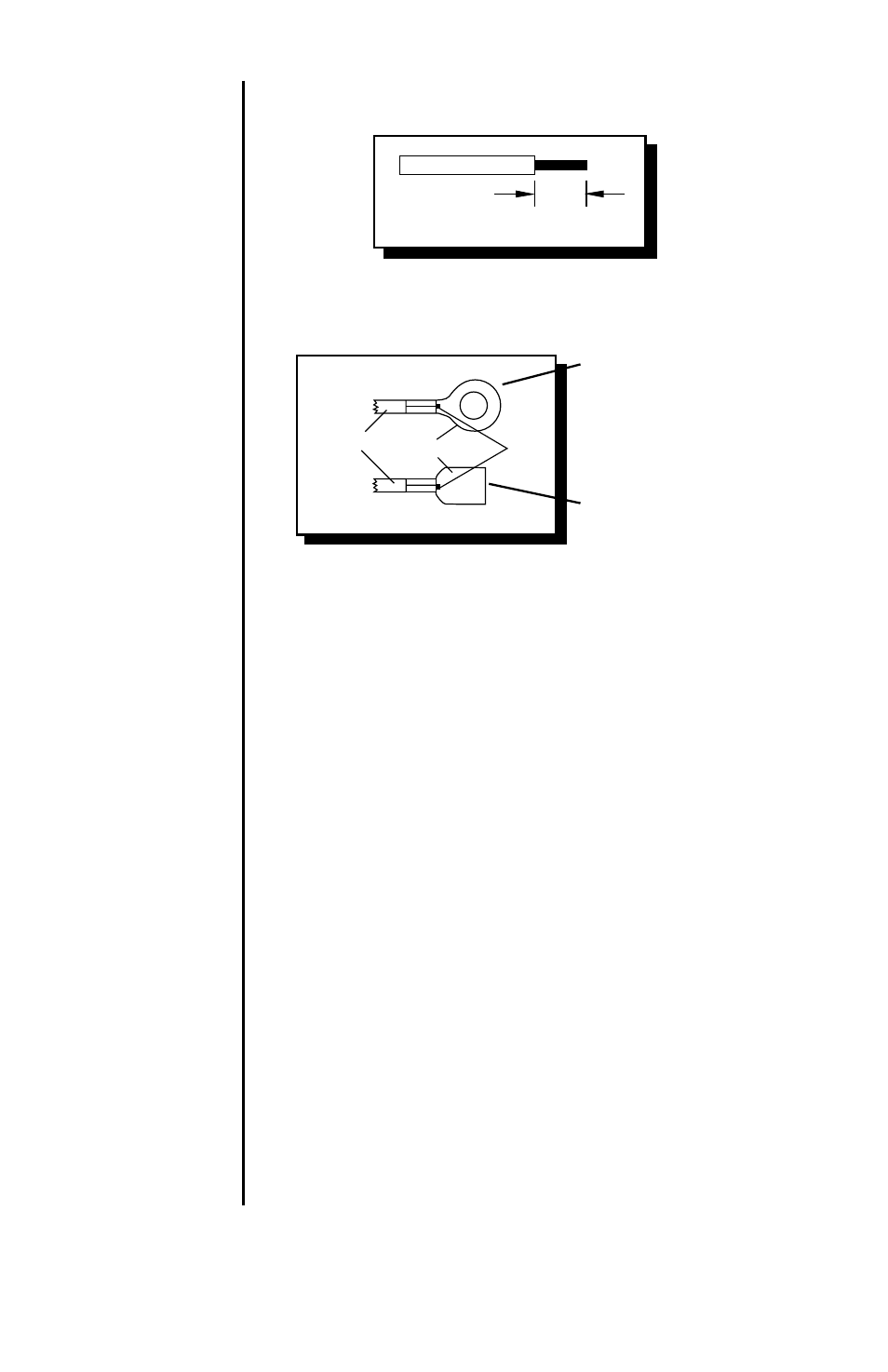
Wiring the
Ring and
Spade
Connectors
1. Strip back approximately 3/8" (1cm) of insulation.
2. Insert the bare wire into the connector and crimp in
place as shown in the following diagram:
3/8"
(1cm)
{
{
Crimp Here
Wire w/insulation
Bare
Wire
Connectors
Crimp Here
This connector is used for
the Red Power wire and
Black Ground wire.
This connector is for the
Blue Remote Turn-On wire.
Power
The gold B+ terminal on the amplifier must be connected
directly
to the positive (+) terminal of the battery with an
appropriate size fuse. (See the Specifications Table for
more information.) This provides a power source with a
low voltage drop and low noise. Be sure to use the
supplied fuse and fuse holder within 18" (46cm) of
the battery’s positive terminal. Failure to do so may
cause damage to the vehicle and the amplifier.
If the power wire must be extended beyond 17' (518cm),
we recommend you use 8 gauge, or heavier, stranded
wire.
If using a larger gauge wire than that supplied with your
new Punch 4-Channel, cut the wire casing on the diago-
nal as shown in the following diagram. Insert the wire into
the connector. Twist the wire around so that the long end
of the insulation faces up. Bend the wire prior to tightening
in place. This will make it easier for attaching the end cap
to the amplifier.
Note: For easier assembly, only 5/8" (1.6cm) of wire
should be bare.
Using Larger
Gauge Wire