Table 3-2, Pin analog i/o connector signal descriptions -4 – National Instruments BNC -2140 User Manual
Page 15
Chapter 3
Signal Connections
3-4
ni.com
Note
This BNC-2140 pin assignment maps to the pin assignment of the DSA device you
are connecting to the BNC-2140. Refer to your DSA device user manual for the pin
assignments specific to your device connection.
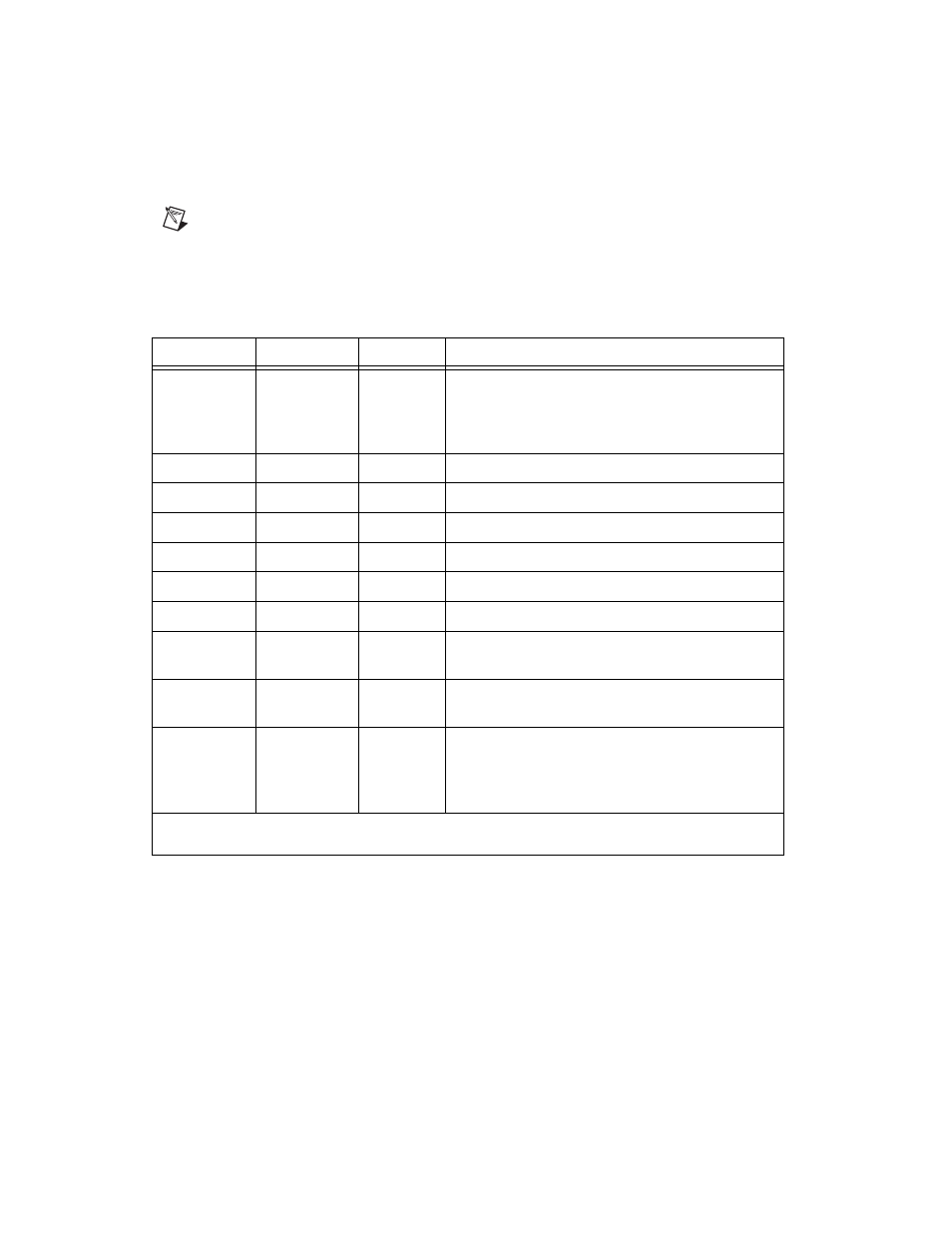
Table 3-2 describes the signals for the internal 68-pin I/O connector.
Refer to Figure 3-1 for the pin assignments for the 68-pin connector.
Table 3-2. 68-Pin Analog I/O Connector Signal Descriptions
Signal Name
Reference
Direction
Description
AIGND
—
—
Analog Input Ground—These pins are the reference
point for single-ended measurements in SE mode
and the bias current return point for differential
measurements.
+ACH<0..3>
AIGND
Input
+Analog Input Channel 0 through 3
–ACH<0..3>
AIGND
Input
–Analog Input Channel 0 through 3
+DAC0OUT
–DAC0OUT
Output
+Analog Output Channel 0
–DAC0OUT
+DAC0OUT
Output
–Analog Output Channel 0
+DAC1OUT
–DAC1OUT
Output
+Analog Output Channel 1
–DAC1OUT
+DAC1OUT
Output
–Analog Output Channel 1
AOGND
—
—
Analog Output Ground—The analog output
voltages are ultimately referenced to this node.
DGND
—
—
Digital Ground—This pin supplies the reference for
the +5 VDC supply.
+5 V
DGND
Output
+5 VDC Source—These pins are fused for up to
0.5 A of +5 V supply on the DSA plug-in device.
The fuse is self-resetting. This source powers the
ICP circuits of the BNC-2140.
Note: For +ACH<0..3>, –ACH<0..3>, +DAC0OUT, –DAC0OUT, +DAC1OUT, and –DAC1OUT descriptions, see
Table 3-1.