Pinout for matrix y-1 cable, Rack mounting instructions – Network Technologies SM-nXm-15V-LCD User Manual
Page 42
NTI VEEMUX VIDEO MATRIX SWITCH
38
Pinout for Matrix Y-1 Cable
Arrows indicate signal direction.
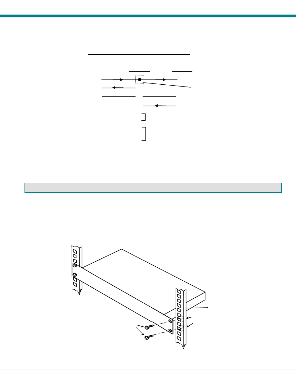
RACK MOUNTING INSTRUCTIONS
This NTI switch was designed to be directly mounted to a rack. It includes a mounting flange to make attachment easy.
Install 4 cage nuts (supplied) to the rack in locations that line up with the holes (or slots) in the mounting flange on the NTI switch.
Then secure the NTI switch to the rack using four #10-32 screws (supplied). Be sure to tighten all mounting screws securely.
Do not block power supply vents in the NTI switch chassis (if provided). Be sure to enable adequate airflow in front of and
behind the NTI switch.
Attach all cables securely to the switch and where necessary supply adequate means of strain relief for cables.
(Unit #1)
(Source)
2
3
3
3
5
5
5
2
2
7
8
1
4
6
Jumper
Jumpers
Not connected to
source connector
(Unit #2)
9D Female
9D Male
9D Male
Wiring Schematic of Matrix-Y-1 cable
Cage Nuts
Rack Screws
Rack
(supplied)
10-32
(supplied)