Sertest- rs232 interface test program, Main options, Matrix operations – Network Technologies SM-nXm-15V-LCD User Manual
Page 15
NTI VEEMUX VIDEO MATRIX SWITCH
11
NTI Switch Control Program For Windows 9X, NT, 2000, XP, Vista And 7
The NTI Switch Control Program is an easy and powerful graphical program that controls NTI matrix switches through an RS232
interface. The NTI Switch Control Program is included on the CD packaged with the VEEMUX. The NTI Switch Control
Program is downloaded by clicking on the link "Download NTI Switch Control Program"
found on the web page that appears
when you insert the instruction manual CD into your CD ROM drive.
To install the NTI Switch Control Program after downloading
1.
Locate the Setup.exe in the directory the program was downloaded to and double-click on it
2.
Follow the instructions on the screen
The NTI Switch Control Program performs best on monitors set to a screen resolution of at least 800 X 600. Instruction for using
the NTI Switch Control Program is available by opening "MSCP Help" in the "NTI" program group once the program has been
installed and is open on the screen.
To open "MSCP Help" from the Windows desktop
1.
Click on
START
2.
Click on
PROGRAMS
3.
Click on
NTI
4.
Click on
MSCP Help
SerTest- RS232 Interface Test Program
This software allows a user to test the functions of an NTI server switch, matrix switch or Multi-user/Multi-platform switch RS232
interface. The program SERTEST along with the NTI Switch Control Program (above) is installed from the CD packaged with
this switch. SERTEST generates a main menu with the 3 selections described below:
Main Options
•
Matrix Operations
- send commands to the matrix unit.
•
Ethernet Operations
- set Ethernet connection variables
•
Setup Options
- set COM port, baud rate, and unit address
•
About SerTest
- display the program version
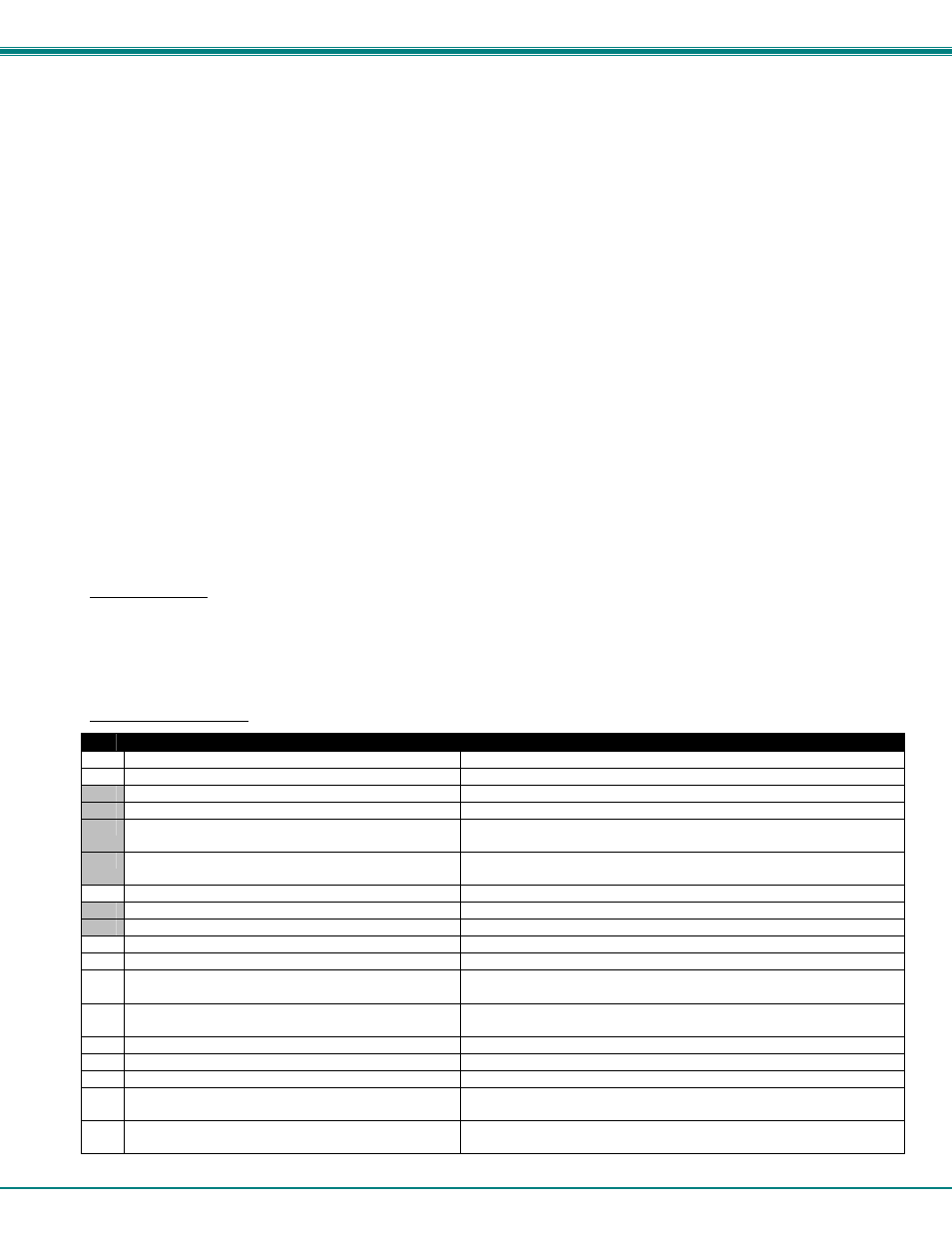
Matrix Operations
Key
Selection
Description
1)
Connect Video Output/User to an Input/CPU
- connect an output to an input
2)
Connect All Video Outputs/Users to an Input/CPU
- connect all outputs to an input
3)
Connect Audio Output/User to an Input/CPU
- connect an output to an input (audio ports only)
4)
Connect All Audio Outputs/Users to an Input
- connect all outputs to an input (audio ports only)
5)
Change Mute Status for Audio Output/User (not
applicable to this unit)
- mute or un-mute the Audio port output
6)
Change Volume for Audio Output/User (not
applicable to this unit)
- change Audio port output volume
7)
Read Connection for Video Output/User
-read the connection of a specific video output
8)
Read Connection for Audio Output/User
-read the connection of a specific audio output
9)
Read Mute and Volume for Audio Output/User
- read the volume and the mute status of the specified audio output
a)
Save I/O Connections into Unit Memory
-save the connections into switch memory bank
b)
Restore I/O Connections from Unit Memory
-restore the connections from switch memory bank
c)
Change All Units Baud Rate (9600/COM1:)
-change RS-232 Baud rate of all switches
-the current baud rate and serial port are displayed in parentheses
d)
Reset Unit
- send a reset command to the switch
- the current unit address is displayed in parentheses
e)
Reset All Units
- send an internal reset command to all switches
f)
Read Unit Size
- read the switch size (number of inputs and outputs)
g)
Read Unit Version/Revision String
-read a string containing the switch version, type, and size
h)
Save All Units I/O Connections into Units Memory
-save the connections into switch memory bank, command for all
switches
i)
Restore All Units I/O Connections from Units
Memory
-restore the connections from switch memory bank, command for all
switches
Selections in the "Key" column that are gray are not applicable to this product.