Top exit / horizontal termination, 90° h – Napoleon Fireplaces GD82NT User Manual
Page 8
8
W45-0536 / C / 09.06.06
H
2
H
1
v
1
90°
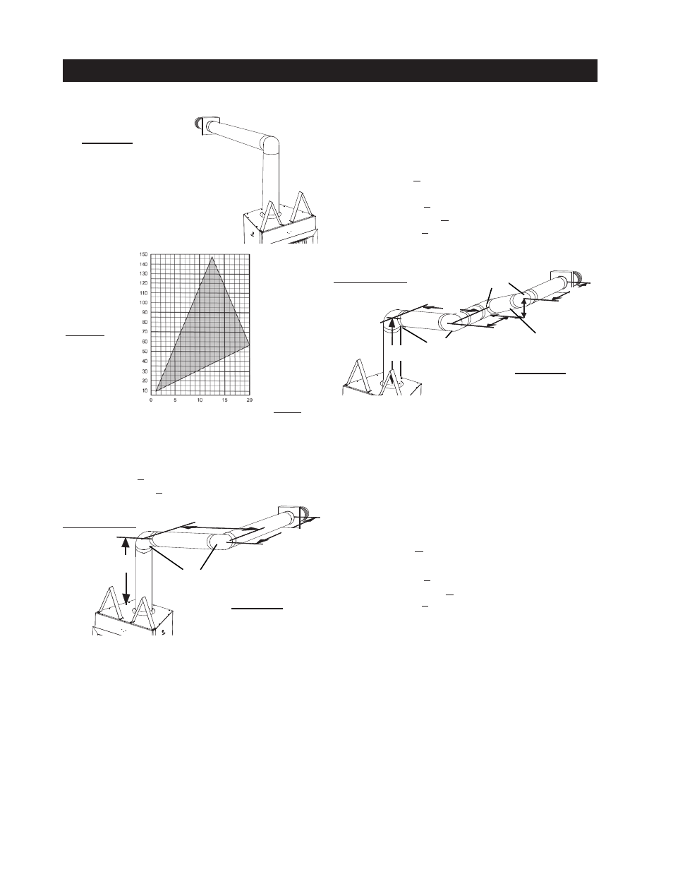
See graph to determine the required verti-
cal rise V
T
for the required horizontal run
H
T
.
v
1
=
v
T
= 6 ft
H
1
= 3 ft
H
2
= 5 ft
H
R
=
H
1
+
H
2
= 3 + 5 = 8 ft
H
O
= .03(two 90° elbows - 90°) = .03(80° - 90°) = .7 ft
H
T
=
H
R
+
H
O
= 8 + .7 = 0.7 ft
H
T
+ v
T
= 0.7 + 6 =6.7
Formula :
H
T
< 4.2 v
T
4.2 v
T
= 4. x 6 = 5. ft
0.7 < 5.
Formula :
H
T
+ v
T
< 24.75 feet
6.7 < 4.75
Since both formulas are met, this vent configuration is ac-
ceptable.
For vent configurations requiring more than one 90° elbow the
following formulas apply:
Formula :
H
T
< 4.
v
T
Formula : H
t
+
v
t
< 4.75 feet
Example 2:
Example 3:
v
1
= 4 ft
v
2
= .5 ft
v
T
=
v
1
+
v
2
= 4 + .5 = 5.5 ft
H
1
= ft
H
2
= ft
H
3
= ft
H
4
= .5 ft
H
R
=
H
1
+
H
2
+
H
3
+
H
4
= + + + . 5 = 5.5 ft
H
O
= .03(four 90° elbows - 90°) = .03(360° - 90°) = 8. ft
H
T
=
H
R
+
H
O
= 5.5 + 8. = 3.6 ft
H
T
+ v
T
= 3.6 + 5.5 = 9. ft
Formula :
H
T
< 4.2 v
T
4.2 v
T
= 4. x 5.5 = 3. ft
3.6 < 3.
Formula :
H
T
+ v
T
< 24.75 feet
9. < 4.75
Since both formulas are met, this vent configuration is
acceptable.
figure 6
figure 7
required
vertical
rise in
inches
v
T
horizontal vent run Plus offset in feet
H
T
figure 8
H
2
H
4
v
2
90°
H
3
H
1
v
1
90°
The shaded area within the lines represents acceptable
values for H
T
and V
T
.
when
(H
T
) > (v
T
)
Simple venting configuration (only one 90° elbow)
TOP EXIT / HORIzONTAL TERMINATION