Front connector – National Instruments SCXI -1122 User Manual
Page 25
Chapter 3
Signal Connections
© National Instruments Corporation
3-3
SCXI-1122 User Manual
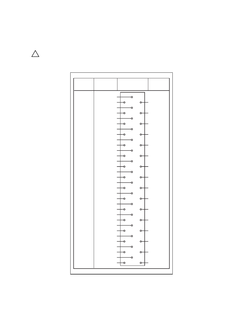
Front Connector
Figure 3-1 shows the pin assignments for the SCXI-1122 front connector.
!
If a relay fails there exists a potential shock hazard on the inputs that are not
in contact with hazardous voltages. For this reason treat all inputs as
potentially hazardous if any inputs are in contact with hazardous voltages
(
≥
30 Vrms, 42.4 Vpk or 60 Vdc).
Pin
Number
Signal
Name
Column
A B C
Signal
Name
32
31
30
29
28
27
26
25
24
23
22
21
20
19
18
17
16
15
14
13
12
11
10
9
8
7
6
5
4
3
2
1
CH+ (0)
RSVD
CH+ (1)
CH+ (2)
CH+ (3)
CH+ (4)
IEX+
CH+ (5)
IEX-
CH+ (6)
VEX+
CH+ (7)
SENSE+
CH+ (8)
SENSE -
CH+ (9)
VEX -
CH+ (10)
CH - (0)
CH - (1)
CH - (2)
CH - (3)
CH - (4)
CH - (5)
CH - (6)
CH - (7)
CH - (8)
CH - (9)
CH - (10)
CH - (11)
CH - (12)
CH - (13)
CH - (14)
CH - (15)
VEX/2
CH+ (11)
CH+ (12)
+5 V
CH+ (13)
CH+ (14)
TEMP+
TEMP-
CH+ (15)
Figure 3-1. SCXI-1122 Front Connector Pin Assignments
- Instrument Driver NI-DMM (12 pages)
- 24-Bit Half/Full-Bridge Analog Input Module NI 9237 (36 pages)
- NI PXIe-8105 (76 pages)
- PXI NI 5401 (60 pages)
- Fieldpoint CFP-2210 (38 pages)
- NI 781xR (48 pages)
- NI 6233 (180 pages)
- 6508 PCI-DIO-96 (93 pages)
- PXI/CompactPCI Embedded Computer NI PXI-8108 (83 pages)
- NI 9233 (34 pages)
- NI USB-9219 (25 pages)
- GPIB-PC (262 pages)
- cFP-RTD-122 (15 pages)
- USB device 625x (23 pages)
- Isolated Analog Input Modules SCC-AI01 (18 pages)
- NI PCI-6111 (118 pages)
- NI USB-6008 (32 pages)
- PC-DIO-24 (75 pages)
- NI 9474 (31 pages)
- NI 6013 (109 pages)
- PXI-1428 (46 pages)
- NI PCI-5911 (51 pages)
- 2 SD Card Memory Module NI 9802 (16 pages)
- cFP-20xx (24 pages)
- NI USB-9234 (23 pages)
- NI 9871 (24 pages)
- Interface Device NI PCI-1426 (35 pages)
- AT E Series (184 pages)
- 9211A (19 pages)
- Module NI PXI-8250 (39 pages)
- 8330 Series (30 pages)
- NI PXIe-8360 (40 pages)
- Deterministic Ethernet Expansion Chassis NI 9144 (65 pages)
- NI 6509 (23 pages)
- NI MATRIXx Xmath (127 pages)
- NI 9481 (23 pages)
- Monochrome Image Acquisition Device NI 1410 (34 pages)
- VXI-1394 (74 pages)
- NI PXI-8104 (69 pages)
- NI 9235 (38 pages)
- 370620B-01 (17 pages)
- FP-RTD-124 (15 pages)
- VXI-USB (61 pages)
- NI PCI-8254R (45 pages)
- Interface Device NI PCI-8254R (16 pages)