Table 4. tb-2709 cabling options, Specifications, Input/output – National Instruments PXI Terminal Block NI TB-2709 User Manual
Page 8
NI TB-2709 Installation Guide
8
ni.com
Table 4 lists the National Instruments cables available for connecting the
TB-2709 to both analog and digital user signals.
Specifications
This section lists the specifications of the TB-2709. These specifications
are typical at 25 °C unless otherwise specified.
Input/Output
Refer to the documentation for your PXI-6123/6133 or PXI-6122/6132
S Series device to determine the input/output specifications for your
application.
Caution
Do not apply an input voltage greater than 42 V
pk
/60 VDC to the TB-2709. Input
voltages greater than 42 V
pk
/60 VDC can damage the TB-2709 and any device connected
to it, including the host computer. Overvoltage can also cause an electric shock hazard for
the operator. National Instruments is not liable for damage or injury resulting from such
misuse.
9
White/Black
P0.5
10
White/Brown
P0.6
11
White/Red
P0.7
12
Drain Wire
CHASSIS GND
13
White/Orange
CTR 1 OUT
14
White/Yellow
PFI 9
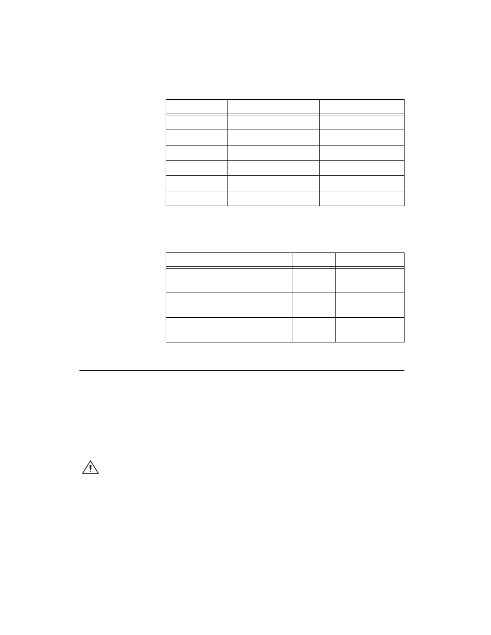
Table 4. TB-2709 Cabling Options
Cable
Length
Part Number
SMB-100, SMB Female to BNC
Female Coaxial, 50
Ω
0.6 m
763389-01
SMB110, SMB to BNC Male
Coaxial, 50
Ω
1 m
763405-01
14-Pos MFIT-Pigtail Cable
Assembly
1 m
194123-01
Table 3. TB-2709 Wiring Information for 14-Pos MFIT-Pigtail
Cable Assembly (Part Number 194123-01) (Continued)
Pin Number
Wire Color
Signal Name