Warning, Servicing / replacements – Napoleon Fireplaces GD82NT-T User Manual
Page 20
20
W415-0666 / 01.28.08
1. Turn off the power to the fi replace.
2. Turn off the gas valve.
3. Remove optional front, glass door, bowl w/ rocks, burner, deco-
rative panel, & burner base.
4. The blower mounting plate can now be removed. Remove the
four screws that secure the plate to the fi rebox base.
5. The blower is secured to the fi rebox. Disconnect the wire con-
nectors before attempting to remove the blower from the fi rebox.
6. Remove the two screws securing the blower and lift through
blower access opening.
Note: When re-installing the replacement blower, it will be necessary
to replace the gasket (W290-0104) on the blower mounting plate.
REMOVE 2 SCREWS
BURNER
BASE
Yo u r
comes equipped with a heat circulating blower. The
blower is pre-wired and is controlled by the remote control supplied
with the unit.
Drywall dust will penetrate into the blower bearings, causing
irreparable damage. Care must be taken to prevent drywall
dust from coming into contact with the blower or its com-
partment. Any damage resulting from this condition is not
covered by the warranty policy.
BLOWER REPLACEMENT
REMOVE 4 SCREWS
BLOWER
MOUNTING PLATE
FIGURE 44
FIGURE 45
!
WARNING
1a. Rectangular Front Removal
Pull on the top of the optional front away from the fi replace until the
male portion of the latch disengages. Tilt forward slightly and lift from
the 2 shoulder screws near the bottom.
1b. Heritage and Wrought Iron Front Removal
Turn the head of each turn button from a horizontal position to verti-
cal. (Fig. 42) Allow the front to tilt forward slightly and lift from the
2 shoulder screws near the bottom front. Note: Fronts are heavy
so when the second turn button is turned the front will want to
fall forward.
OPTIONAL FRONT REMOVAL
FIGURE 42
Lift the panel from the slots. This will allow access and removal of
the remote receiver and spark module.
If valve replacement is necessary follow step 1 above then proceed
with the following ...
Remove the 6 screws that secure the burner base. Once the gas has
been disconnected, the burner train assembly will lift out. (Fig. 38)
Start by sliding the bowl forward until it clears the burner then lift from
the fi rebox. Remove the 2 screws located behind the burner then lift
up off the orifi ce and out. Then using a fl at head screw driver remove
the curved decorative panel. Finally remove the 2 screws holding
the burner base in place.
(Fig. 45)
Lift the burner out from the fi rebox.
CONTROL PANEL REMOVAL
BOWL AND BURNER REMOVAL
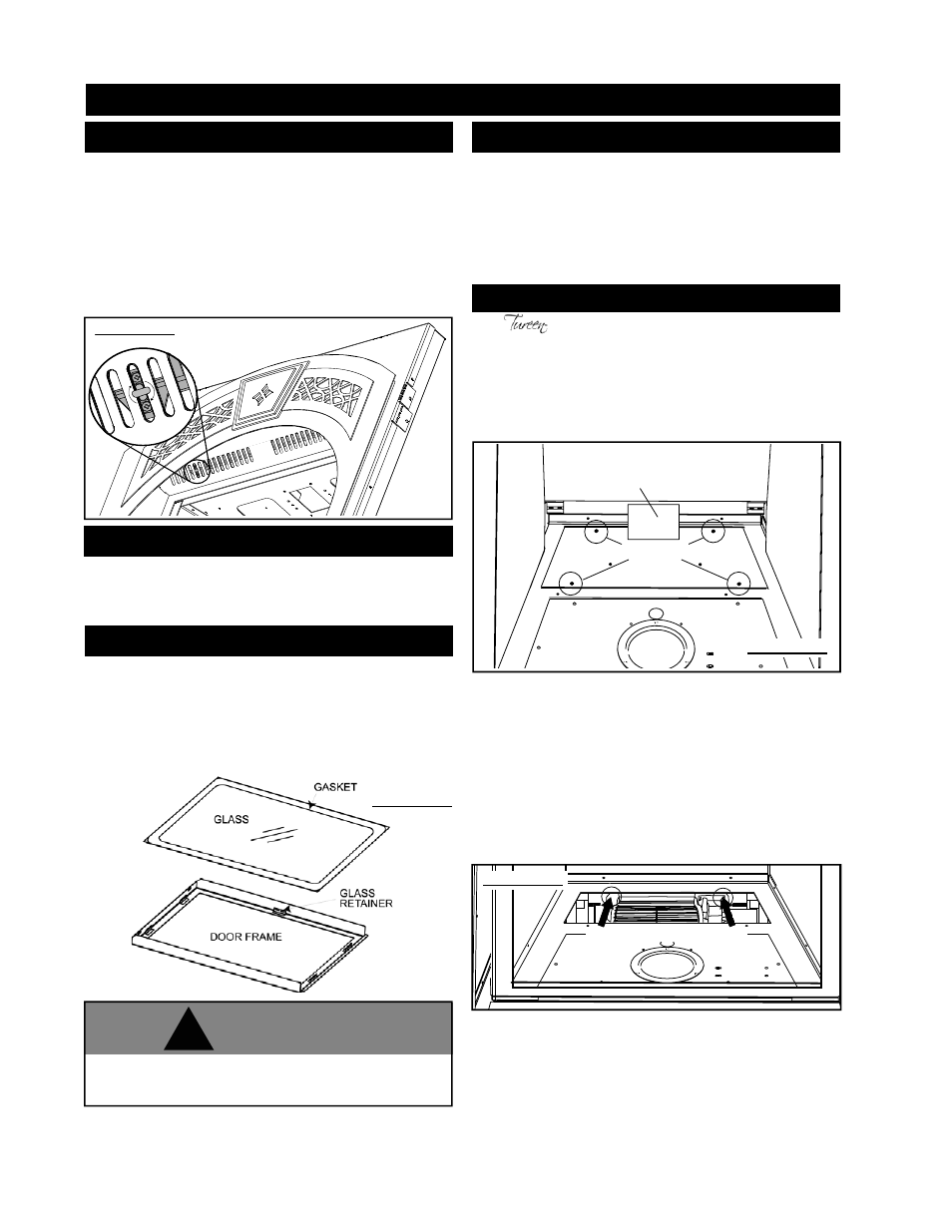
1. Place the door frame face down careful not to scratch the
paint.
2. Center the gasketed glass inside the door frame with the thick
side of the gasket facing up.
3. Bend the glass retainers located along the edge of the door
frame over the gasket holding the glass in place. Careful not to
break the glass.
GLASS/DOOR REPLACEMENT
FIGURE 43
Care must be taken when removing and disposing of any broken
glass or damaged components. Be sure to vacuum up any broken
glass from inside the fi replace before operation.
SERVICING / REPLACEMENTS