Figure 2-1. removing protective screw caps – National Instruments NI PXI-8104 User Manual
Page 16
Chapter 2
Installation and Configuration
2-2
ni.com
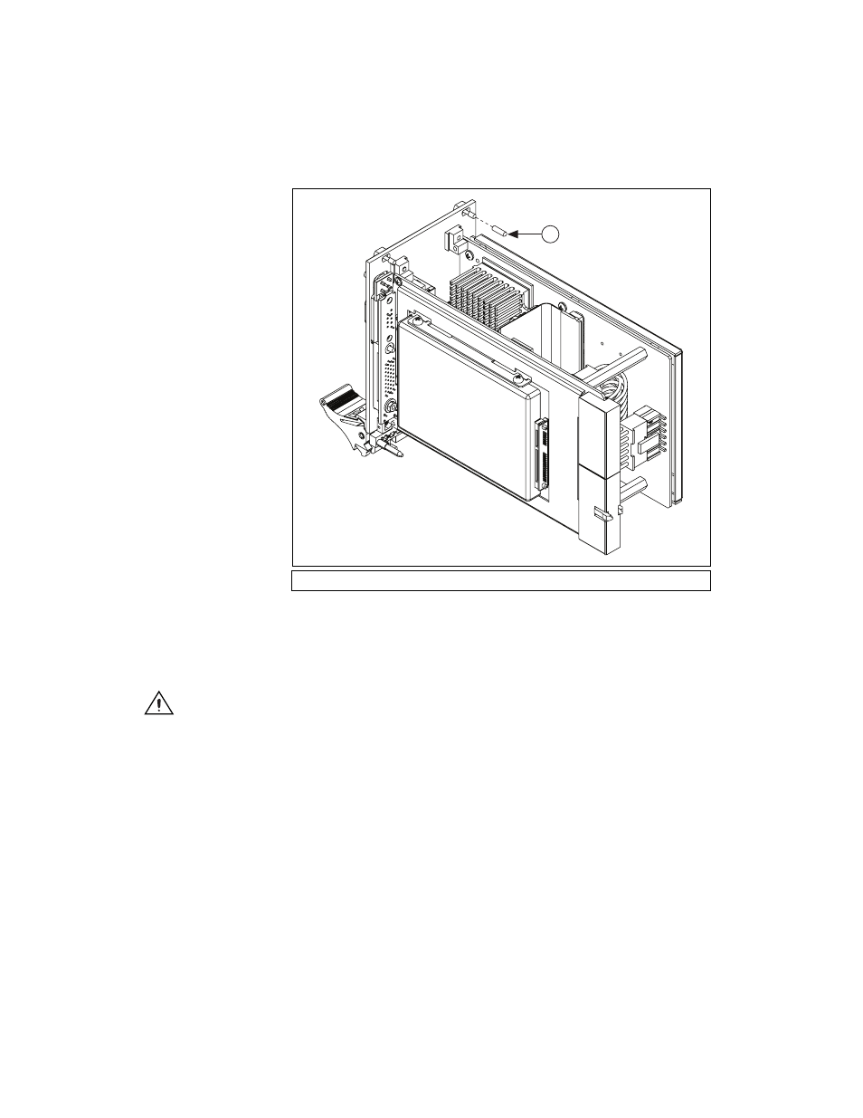
Figure 2-1. Removing Protective Screw Caps
5.
Make sure the injector/ejector handle is in its downward position.
Align the NI PXI-8104 with the card guides on the top and bottom
of the system controller slot.
Caution
Do not raise the injector/ejector handle as you insert the NI PXI-8104.
The module will not insert properly unless the handle is in its downward position so
that it does not interfere with the injector rail on the chassis.
6.
Hold the handle as you slowly slide the module into the chassis until
the handle catches on the injector/ejector rail.
7.
Raise the injector/ejector handle until the module firmly seats
into the backplane receptacle connectors. The front panel of the
NI PXI-8104 should be even with the front panel of the chassis.
8.
Tighten the four bracket-retaining screws on the top and bottom of the
front panel to secure the NI PXI-8104 to the chassis.
9.
Check the installation.
1
Protective Screw Cap (4X)
1