Figure b-2. pcmcia-can bus-powered cable, Figure b-3. pinout for 9-pin d-sub connector – National Instruments NI-DNET User Manual
Page 62
Appendix B
Cabling Requirements
B-2
ni.com
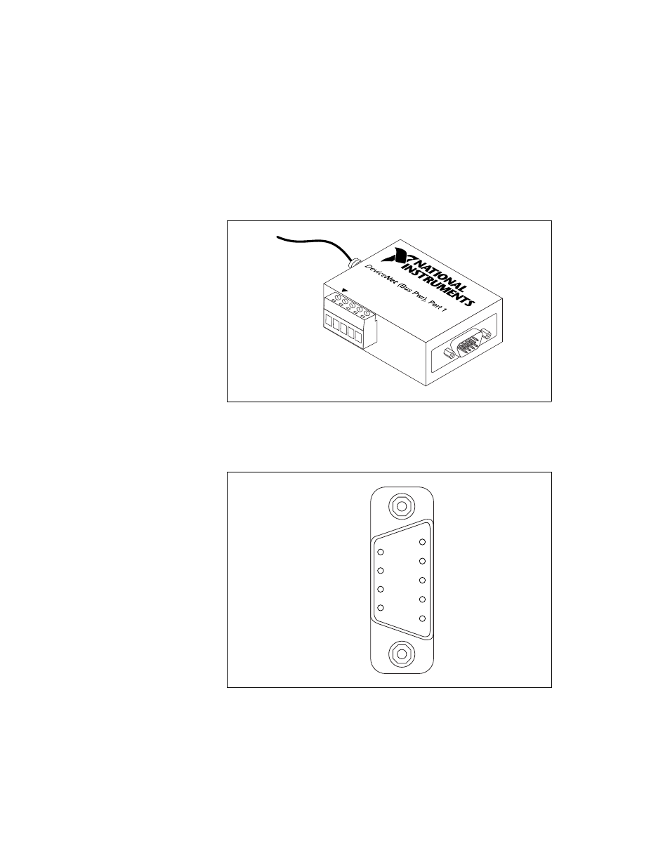
Figure B-2 shows the end of a PCMCIA-CAN bus-powered cable. The
arrow points to pin 1 of the 5-pin screw terminal block. All of the signals
on the 5-pin Combicon-style pluggable screw terminal are connected
directly to the corresponding pins on the 9-pin D-SUB following the pinout
in Figure B-3.
Figure B-2. PCMCIA-CAN Bus-Powered Cable
The 9-pin D-SUB follows the pinout recommended by CiA Draft
Standard 102. Figure B-3 shows the pinout for this connector.
Figure B-3. Pinout for 9-Pin D-SUB Connector
J2
J1
V-
C_L
SH
C_H
V+
1
234
5
6
789
No Connection
CAN_L
V–
No Connection
Optional Ground (V–)
CAN_H
No Connection
V+
Shield
See also other documents in the category National Instruments Hardware:
- Instrument Driver NI-DMM (12 pages)
- 24-Bit Half/Full-Bridge Analog Input Module NI 9237 (36 pages)
- NI PXIe-8105 (76 pages)
- PXI NI 5401 (60 pages)
- Fieldpoint CFP-2210 (38 pages)
- NI 781xR (48 pages)
- NI 6233 (180 pages)
- 6508 PCI-DIO-96 (93 pages)
- PXI/CompactPCI Embedded Computer NI PXI-8108 (83 pages)
- NI 9233 (34 pages)
- NI USB-9219 (25 pages)
- GPIB-PC (262 pages)
- cFP-RTD-122 (15 pages)
- USB device 625x (23 pages)
- Isolated Analog Input Modules SCC-AI01 (18 pages)
- NI PCI-6111 (118 pages)
- NI USB-6008 (32 pages)
- PC-DIO-24 (75 pages)
- NI 9474 (31 pages)
- NI 6013 (109 pages)
- PXI-1428 (46 pages)
- NI PCI-5911 (51 pages)
- 2 SD Card Memory Module NI 9802 (16 pages)
- cFP-20xx (24 pages)
- NI USB-9234 (23 pages)
- NI 9871 (24 pages)
- Interface Device NI PCI-1426 (35 pages)
- AT E Series (184 pages)
- 9211A (19 pages)
- Module NI PXI-8250 (39 pages)
- 8330 Series (30 pages)
- NI PXIe-8360 (40 pages)
- Deterministic Ethernet Expansion Chassis NI 9144 (65 pages)
- NI 6509 (23 pages)
- NI MATRIXx Xmath (127 pages)
- NI 9481 (23 pages)
- Monochrome Image Acquisition Device NI 1410 (34 pages)
- VXI-1394 (74 pages)
- NI PXI-8104 (69 pages)
- NI 9235 (38 pages)
- 370620B-01 (17 pages)
- FP-RTD-124 (15 pages)
- VXI-USB (61 pages)
- NI PCI-8254R (45 pages)
- Interface Device NI PCI-8254R (16 pages)