Philips SAA7345 User Manual
Page 22
1998 Feb 16
22
Philips Semiconductors
Product specification
CMOS digital decoding IC with RAM for
Compact Disc
SAA7345
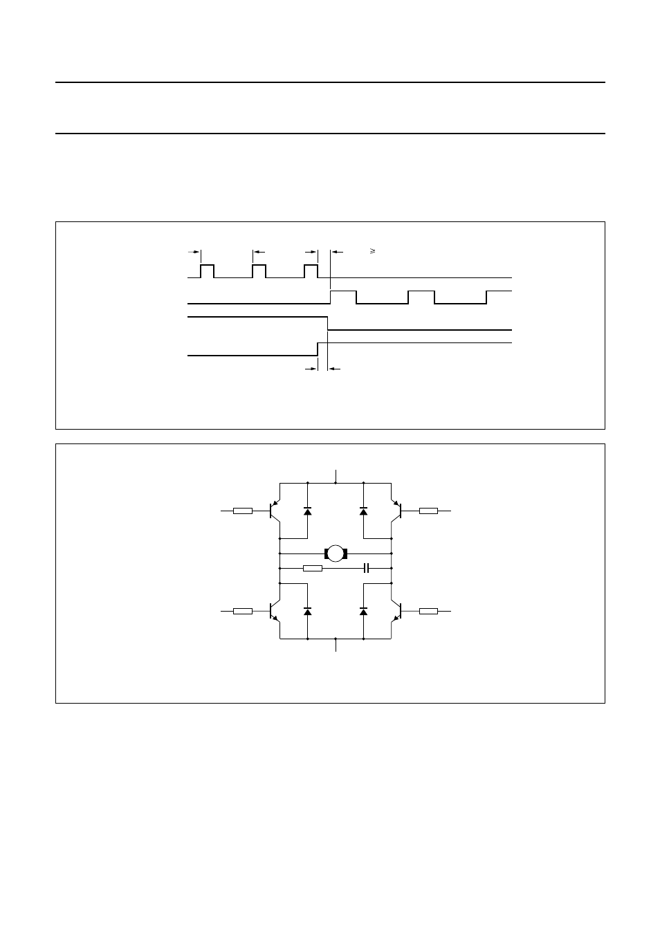
PWM
MODE
, 4-
LINE
Using two extra outputs from the Versatile Pins Interface, it is possible to use the SAA7345 with a 4-input motor bridge.
Figure 19 shows the timing and Fig.20 a typical application diagram.
CDV
MODE
In the CDV motor mode, the FIFO position will be put in pulse-width modulated form on the MOTO1 pin (carrier frequency
300 Hz) and the PLL frequency signal will be put in pulse-density modulated form on the MOTO2 pin (carrier frequency
4.23 MHz). The integrated motor servo is disabled in this mode.
Remark:
The PWM signal on MOTO1 corresponds to a total memory space of 20 frames, therefore the nominal FIFO position
(half-full) will result in a PWM output of 60%.
Fig.19 Motor 4-line PWM mode timing.
MOTO1
MOTO2
V4
V5
rep
t = 45
µ
s
t 240 ns
dead
ovl
t = 240 ns
Accelerate
Brake
MGA367 - 1
MGA364 - 2
VSS
+
M
MOTO1
V4
MOTO2
V5
100 nF
10
Ω
Fig.20 Motor 4-line PWM mode application diagram.
- SWA3301S/17 (1 page)
- Duplex SDJ6130W (2 pages)
- Swarovski SW60/27 (2 pages)
- PSC705 (34 pages)
- SNA6500 (47 pages)
- PSC702 (2 pages)
- PSC70217 (2 pages)
- SWV2591W (2 pages)
- 3LR12PBXC/10 (2 pages)
- PCA102CD (47 pages)
- S26.7912-006 (1 page)
- VOIP080IB (2 pages)
- PSC 604 (10 pages)
- HAPPY LAURA FM02SW00/00 (2 pages)
- WAR1900 (2 pages)
- SWV3558 (2 pages)
- FM01SW60 (72 pages)
- SWV3458W/17 (2 pages)
- SPE3071CC (2 pages)
- SWV4157W (2 pages)
- SPD5240 (51 pages)
- PH0900L (29 pages)
- Swarovski FM01SW40/00 (2 pages)
- FM02FD02B/00USB (2 pages)
- CGA7740N (26 pages)
- SNA6640 (42 pages)
- SJM2121 (2 pages)
- US2-P72069 (2 pages)
- FM02SW00 (104 pages)
- Mercury 1314L2S (2 pages)
- PHOTOFRAME 7FF1CWO (51 pages)
- SDJ6070W (2 pages)
- SJA9480 (2 pages)
- SWV3011W (2 pages)
- SCU5120NB (2 pages)
- TDA6800 (10 pages)
- SHOWVIEW VR400 (2 pages)
- SWV3459W/17 (2 pages)
- SWV3458W/27 (2 pages)
- Swarovski FM01SW21/00 (2 pages)
- TDA8767 (20 pages)
- SAA2051W (2 pages)
- SPE2010CC (2 pages)
- SCU3050NB (2 pages)
- SDJ6120W (2 pages)