Ebu interface – Philips SAA7345 User Manual
Page 19
1998 Feb 16
19
Philips Semiconductors
Product specification
CMOS digital decoding IC with RAM for
Compact Disc
SAA7345
EBU interface
The biphase-mark digital output signal at pin DOBM is in accordance with the format defined by the
“IEC 958”
specification.
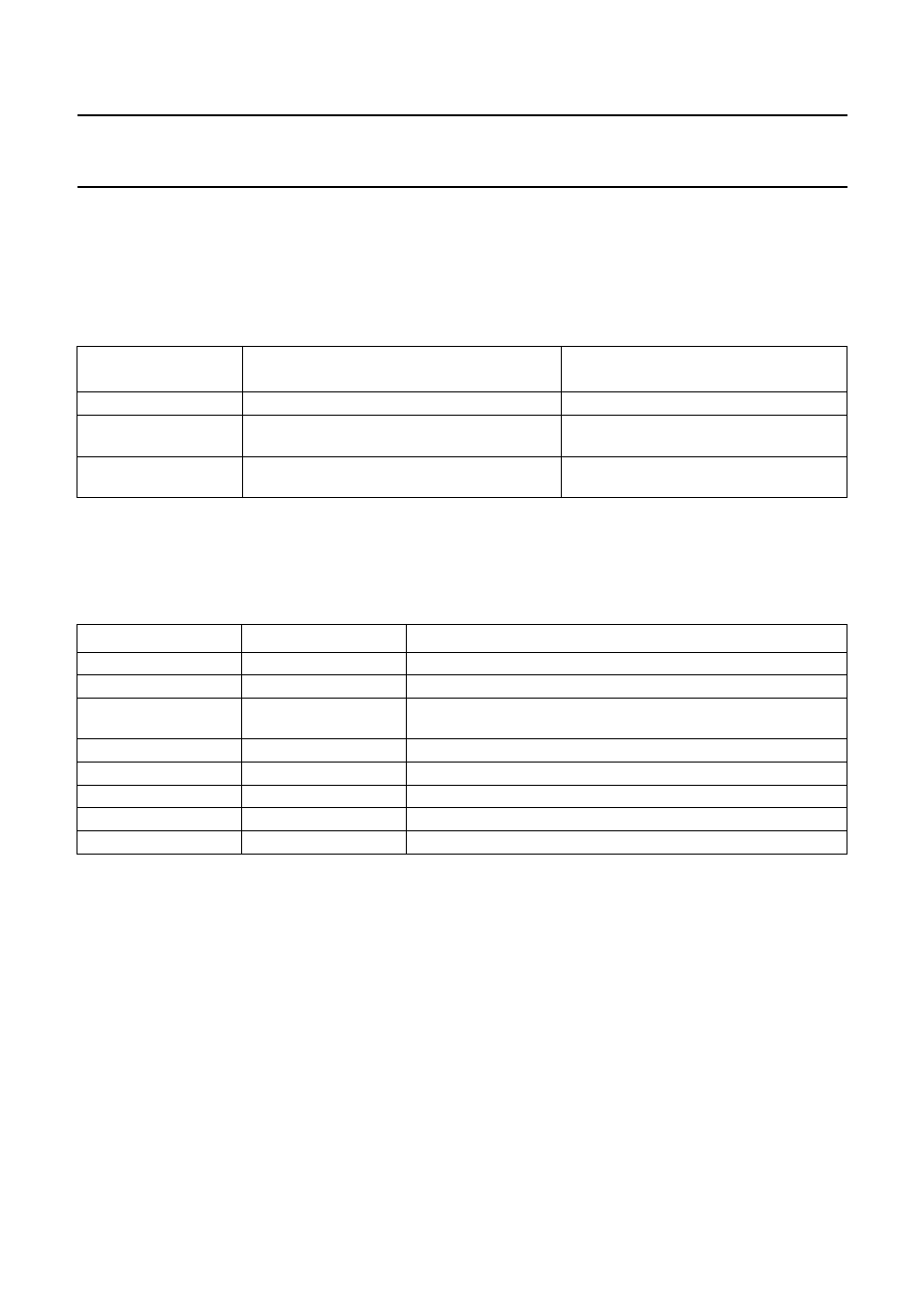
Three different modes can be selected via the EBU output control register (address 1010).
Table 6 EBU output modes
F
ORMAT
The digital audio output consists of 32-bit words (subframes) transmitted in biphase-mark code (two transitions for a
logic 1 and one transition for a logic 0). Words are transmitted in blocks of 384 (see Table 7).
Table 7 EBU word format
EBU CONTROL
REGISTER DATA
EBU OUTPUT AT DOBM PIN
EBU VALIDITY FLAG (BIT 28)
X X 1 1
DOBM pin held LOW
−
X X 0 0
data taken before concealment, mute and fade
HIGH if data is non-correctable
(concealment flag)
X X 1 0
data taken after concealment, mute and fade
HIGH if data is non-correctable
(concealment flag)
WORD
BITS
FUNCTION
Sync
0 to 3
−
Auxiliary
4 to 7
not used; normally zero
Error flags
4
CFLG error and interpolation flags when bit 3 of EBU control
register is set to logic 1
Audio sample
8 to 27
first 4 bits not used (always zero)
Validity flag
28
valid = logic 0
User data
29
used for subcode data (Q-to-W)
Channel status
30
control bits and category code
Parity bit
31
even parity for bits 4 to 30
S
YNC
The sync word is formed by violation of the biphase rule
and therefore does not contain any data. Its length is
equivalent to 4 data bits. The three different sync patterns
indicate the following situations:
•
Sync B:
– Start of a block (384 words), word contains left
sample.
•
Sync M:
– Word contains left sample (no block start).
•
Sync W:
– Word contains right sample.
A
UDIO SAMPLE
Left and right samples are transmitted alternately.
V
ALIDITY FLAG
Audio samples are flagged (bit 28 = logic 1) if an error has
been detected but was non-correctable. This flag remains
the same even if data is taken after concealment.
U
SER DATA
Subcode bits Q-to-W from the subcode section are
transmitted via the user data bit. This data is asynchronous
with the block rate.