Identify the status leds, Power, Link 1/lan 2 – Perle Systems IOLINK-520 User Manual
Page 19: Link 2
Applications
IOLINK-520 & IOLINK-PRO Installation & Applications Guide — 1.9
Identify the Status LEDs
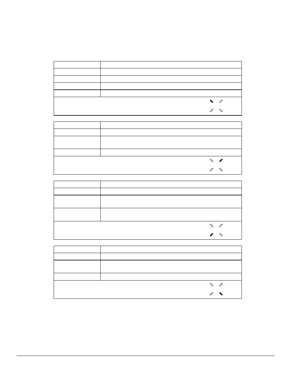
The four three colour Light Emitting Diodes (LEDs) on the front of the IOLINK router
are depicted in Figure 1-1. The meanings of these LEDs are found in the following chart.
Off
Bridge/Router is powered down
Green
Bridge/Router is running and has passed power-up diagnostics
Green (flashing)
Bridge/Router is in BOOT mode and is programming the flash
Red
Bridge/Router is powered up but has failed power-up diagnostics
Yellow (flashing)
Bridge/Router is in BOOT mode
POWER
Off
Module is not installed
Green
Module is connected and forwarding
Yellow
LAN is connected and NOT forwarding:
i.e. Listening, Learning, or Blocking
Red
Bridge/Router is NOT connected to the LAN
LAN
Off
Module is not installed or is configured to be down: Disabled.
Green
Connection is up* / LAN 2 connected and forwarding
Yellow
LINK is negotiating in ISDN. LINK is auto-learning LMI type
in Frame Relay. Not used in Leased Line or LAN mode
Red
Software failure (if WAN module installed)
LAN 2 not connected (if LAN2 module installed)
LINK 1/LAN 2
Off
Module is not installed or is configured to be down: Disabled.
Green
Connection is up*
Yellow
LINK is negotiating in ISDN. LINK is auto-learning LMI type
in Frame Relay. Not used in Leased Line mode
Red
Software failure
LINK 2
*If the module is an ISDN BRI interface, a connection on either B-channel will display a
green LED.