Bbu he technical specification, Bermuda bbu he – Baxi Potterton BERMUDA BBU HE User Manual
Page 8
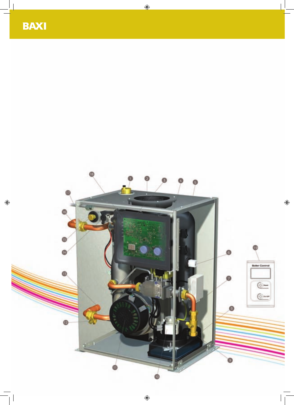
BBU HE Technical Specification
The 3D diagram below displays the key components of the Baxi Bermuda BBU HE.
1. Automatic Air Vent
11. Fan
2. Flue Connection
12. Drain
3. Spark Generator (located behind PCB)
13. Return Connection
4. Spark & Sensing Electrodes (located behind PCB)
14. Air Sampling Point
5. Heat Exchanger (located behind PCB)
15. Flue Sampling Point
6. User Interface Connector
16. Flow Connection
7. Control Wiring Connector
17. Condensate Outlet
8. Condensate Sump
18. PCB Control Box
9. Gas Cock
19. Boiler Control (cover open)
10. Condensate Pump
Bermuda BBU HE
8
372075-03.indd 8
01/06/2010 14:35