Connecting the tv-video combi – Philips 14PV385/07 User Manual
Page 6
4
EN
Important for the United Kingdom
This apparatus is fitted with a BS1362 5 Amp
inside an approved moulded 13 Amp plug.
To replace a fuse in this type of plug proceed as
follows:
1.
1.
Remove fuse cover and fuse.
2.
2.
Fix new fuse which should be a BS1362 5A,
ASTA or BSI approved type.
3.
3.
Refit the fuse cover.
If the fitted plug is not suitable for your socket
outlets, it should be cut off and an appropriate
plug fitted in its place. If the mains plug contains
a fuse, this should have a value of 5A. If a plug
without a fuse is used, the fuse at the distribu-
tion board should not be greater than 5A.
How to connect a plug:
The wires in the mains lead are coloured in
accordance with the following code:
BLUE- ‘NEUTRAL’ (‘N’)
BROWN- ‘LIVE’ (‘L’)
4.
4.
The BLUE wire must be connected to the ter-
minal which is marked with the letter ‘N’ or
coloured BLACK.
5.
5.
The BROWN wire must be connected to the
terminal which is marked with the letter ‘L’ or
coloured RED.
6.
6.
Do not connect either wires to the earth ter-
minal in the plug which is marked with the let-
ter ‘E’ or by the safety earth symbol
or
coloured green or green-and-yellow.
Before replacing the plug cover, make certain
that the cord grip is clamped over the sheath of
the lead-not simply over the two wires
Preparing the remote control for
operation
The remote control and its batteries are packed
separately in the original TV-Video Combi pack-
aging. You must install the batteries in the
remote control before use.
1.
1.
Take the remote control and the enclosed
batteries (2 batteries).
2.
2.
Open the remote control’s battery compartment
and place the batteries in it as shown in the
picture and close the battery compartment.
The remote control is now ready to use. Its
range is approximately 7 metres.
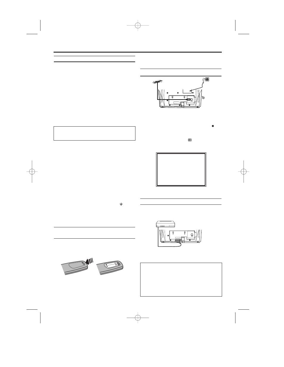
Connecting the cable
1.
1.
Insert the aerial cable plug into the AERIAL
at the back of the TV-Video Combi.
2.
2.
Connect the mains cable to the wall socket.
3.
3.
If the little red standby light (STANDBY
) at
the front panel of the set is not lit, please
switch on the set using the main power
switch. The power switch
is located on the
left side panel of the set.
4.
4.
The following screen will appear on the TV.
You can find more details in chapter ‘Preparation
for use’.
Connecting additional devices
You can connect additional devices such as
decoders, satellite receivers, camcorders, etc. to
the EXT1/ AV1 socket.
1. Connecting the TV-Video Combi
The severed plug must be destroyed to avoid a
possible shock hazard, or should it be inserted
into a 13A socket elsewhere.
PLEASE CONNECT AERIAL OR
CABLE TO THE TVCR
THEN...
PUSH P+ KEY
OR...
FOR PLAY ONLY PUSH PLAY
The respective scart socket is usually marked ‘AV’
or ‘TV’ on the decoder or satellite receiver.
Selection of the scart socket
• To select the Scart socket, please enter 0,0,1,
with the keys on the remote control. AV1
appears on the screen.
Selection of the front A/V sockets
• To select the front A/V sockets, please enter
0,0,2, with the keys on the remote control.
‘AV2’ appears on the screen.
T6450EZ(EN)_UKX.qx3 04.2.12 9:23 PM Page 6