3 can – PEAK-System Technik RS-232 User Manual
Page 12
PCAN-USB Hub – User Manual
12
Figure 1: Power socket at the rear of the PCAN-USB Hub
for the external voltage supply (self-powered operation)
The connection of an external power supply at the power socket is
done with the supplied mating connector for fastening cable
strands.
3.3
CAN
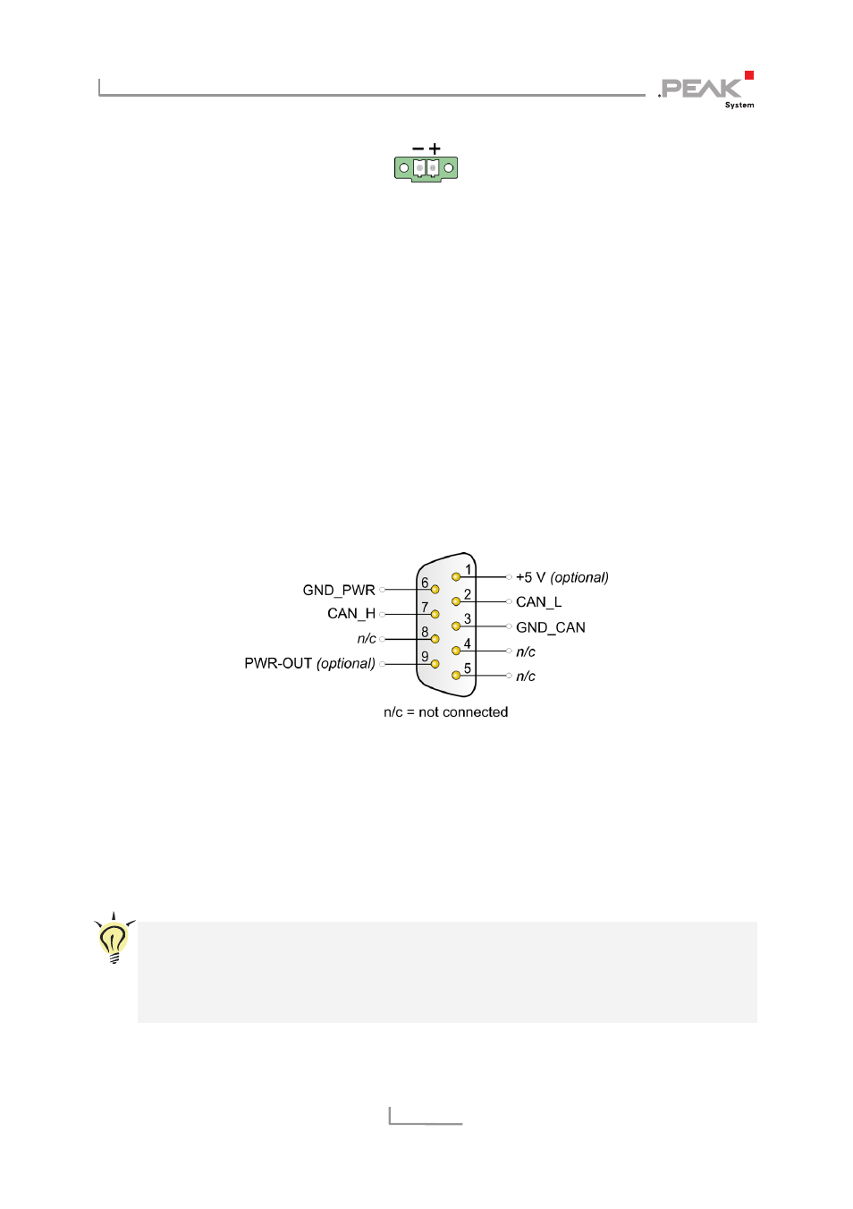
A High-speed CAN bus (ISO 11898-2) is connected to the 9-pin
D-Sub connector. The pin assignment for CAN corresponds to the
specification CiA® 102.
Figure 2: Pin assignment High-speed CAN
(view onto connector of the PCAN-USB Hub)
With the pins 1 and 9 devices with low power consumption (e.g. bus
converters) can be directly supplied via the CAN connector. At
delivery these pins are not assigned. You can find a detailed
description about the activation in the following section 3.3.1.
Tip: You can connect a CAN bus with a different transmission
standard via a bus converter. PEAK-System offers different bus
converter modules (e.g. PCAN-TJA1054 for a Low-speed CAN
bus according to ISO 11898-3).