Patton electronic 1012ARC User Manual
Page 3
2.0 GENERAL INFORMATION
Thank you for your purchase of this Patton Electronics product.
This product has been thoroughly inspected and tested and is
warranted for One Year parts and labor. If any questions or problems
arise during installation or use of this product, please do not hesitate to
contact Patton Electronics Technical Support at (301) 975-1007.
2.1 FEATURES
• Houses two short range modems
• Full or half duplex
• Asynchronous data rates to 38.4 Kbps
• Point-to-point or multipoint
• Automatic equalization and gain control
• Software and hardware handshaking
• Distances to 6 miles over two unconditioned twisted pair
• Transformer isolation
• Silicon Avalanche Diode surge protection
• Mounts in Patton’s rack chassis
• Made in USA
2.2 DESCRIPTION
The Patton Model 1012ARC is a miniature rack card designed to
house two asynchronous short range modems. Operating full or half
duplex at data rates to 38.4 Kbps, the Model 1012ARC supports point-
to-point or multidrop applications and offers automatic equalization and
gain control. The Model 1012ARC supports distances up to 6 miles
over two twisted pair. Built-in transformer isolation and surge
protection provide protection against ground potential differences and
AC/DC over-voltages, making the Model 1012ARC ideal for
connections between two buildings.
The Model 1012ARC is designed to mount in Patton’s Model
1000R16P rack chassis. This 16-card chassis has a switchable
120/240 volt power supply and uses mid-plane architecture: The front
card can be plugged into different rear cards. This means that the
1012ARC can have several interface options, and can be switched with
other Patton short haul cards. The rear card is available with an RJ-45
connection for each RS-232 channel and either RJ-11 or RJ-45
connections for twisted pair.
3
3.0 CONFIGURATION
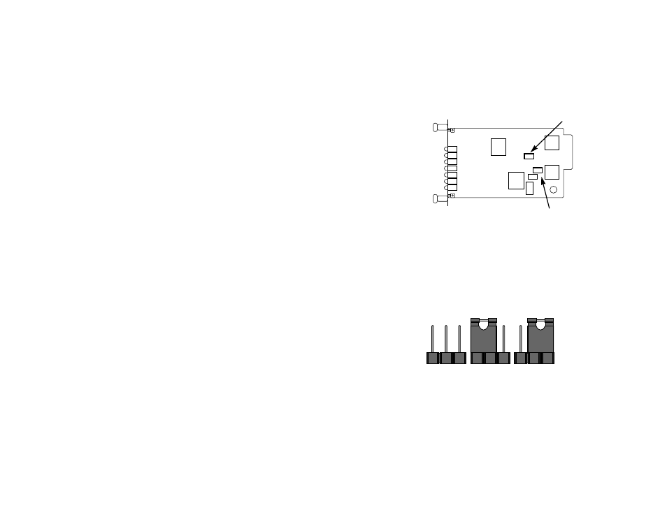
The Model 1012ARC rack card is easy to set up since there are
only two configuration straps. Figure 1 (below) shows the location of
these straps on the Model 1012ARC PC board.
3.1 MOVING THE CONFIGURATION STRAPS
Figure 2 shows how to move the configuration straps. Note that the
Model 1012ARC only has two pegs, thus the straps can only be
“installed” or “removed”. The rear card uses three pegs, and can be on
either pegs 1 and 2, or pegs 2 and 3.
3.2 SETTING THE RTS/DCD STRAPS
Each RTS/DCD strap affects one of your modems. Their setting
determines how the respective transmitters (i.e., carrier) are activated.
When these straps are installed, the Model 1012ARC transmitter is
CONTROLLED CARRIER. When these straps are removed, the
transmitter is CONSTANT CARRIER. Each strap may be configured
separately.
4
Figure 1. Model 1012ARC, showing straps locations
RTS Channel A
RTS Channel B
Figure 2. Orientation of interface card straps
1
2
3
1
2
3
1
2
3