0 installation, 1 connecting dsl interface, Dsl interface – Patton electronic 1082 User Manual
Page 17: Interface connector power input connector
17
5.0 INSTALLATION
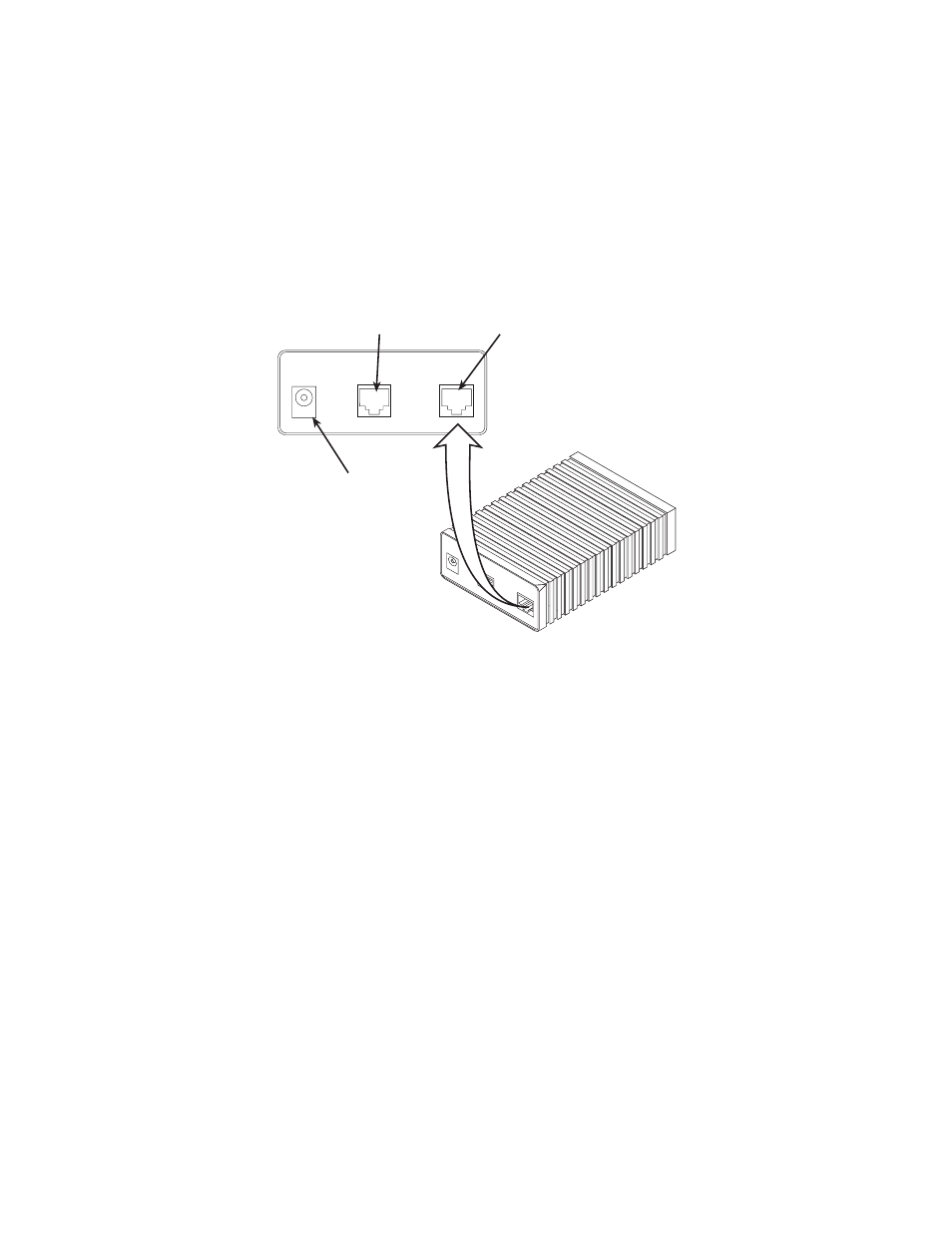
When the Model 1082 has been properly configured, it may be con-
nected to the DSL twisted pair interface, the 10Base-T Ethernet Inter-
face, and the power source. This section describes these connections.
Figure 6.
Model 1082/I or Model 1082/144/I rear view
5.1 CONNECTING DSL INTERFACE
The Model 1082 supports communication between 10Base-T Hubs or
Workstations at distances to 5 miles (8 km) over 24 AWG (.5mm) twisted
pair wire. There are two requirements for installing the Model 1082:
• These units operate as a pair. Both units at the end of the twisted pair
DSL span must be set for the same DTE rate.
• To function properly, the Model 1082 needs one twisted pair of metallic
wire. This twisted pair must be unconditioned, dry, metallic wire,
between 19 (.9mm) and 26 AWG (.4mm) (the higher number gauges
will limit distance). Standard dial-up telephone circuits, or leased cir-
cuits that run through signal equalization equipment, or standard, flat
modular telephone type cable, are not acceptable.
G.703/G.704 T
est
Modes
511E
Model 1194E Single Mode Fiber - Quad G.703/G.704 Modem
Interface
Power
Made in the USA
DSL
ON
OFF
|
O
DSL
DSL interface
Power
Interface
Made in the USA
Interface connector
Power input
connector