0 configuration, 1 configuring the hardware dip switches – Patton electronic 1082 User Manual
Page 11
11
4.0 CONFIGURATION
The Model 1082/I and Model 1082/144/I each are equipped with 16 DIP
switches that enable configuration of the unit for a wide variety of appli-
cations. This section describes switch locations and explains the different
configurations.
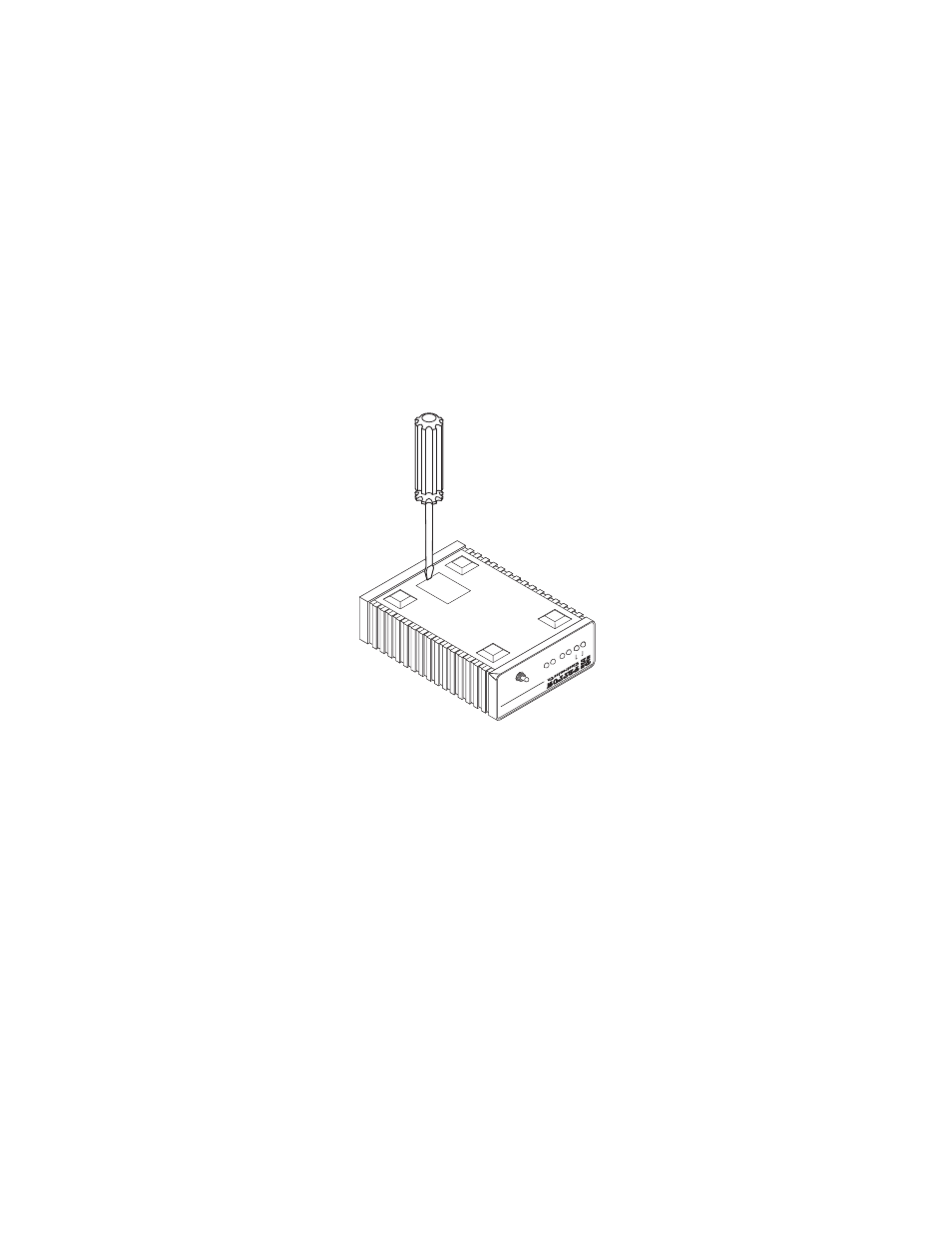
4.1 CONFIGURING THE HARDWARE DIP SWITCHES
Using a small flat-tip screwdriver, remove the protective cover located on
the underside of the Model 1092 (see Figure 4).
Figure 4.
Removing the cover to access DIP switches S1 and S2
511
G.703/G.704 T
est
Modes
511E
Model 1194E Single Mode Fiber - Quad G.703/G.704 Modem
511/RDL
TM
ER
NS
Status
NetLink 10BastT iDSL Modem
10BT
DSL
Normal
511E/RBL
Link