Figure 1-12: hfg2.0 system signal wiring diagram – Hamilton Sundstrand Company Gas Fuel Metering Valve HFG2.0 User Manual
Page 25
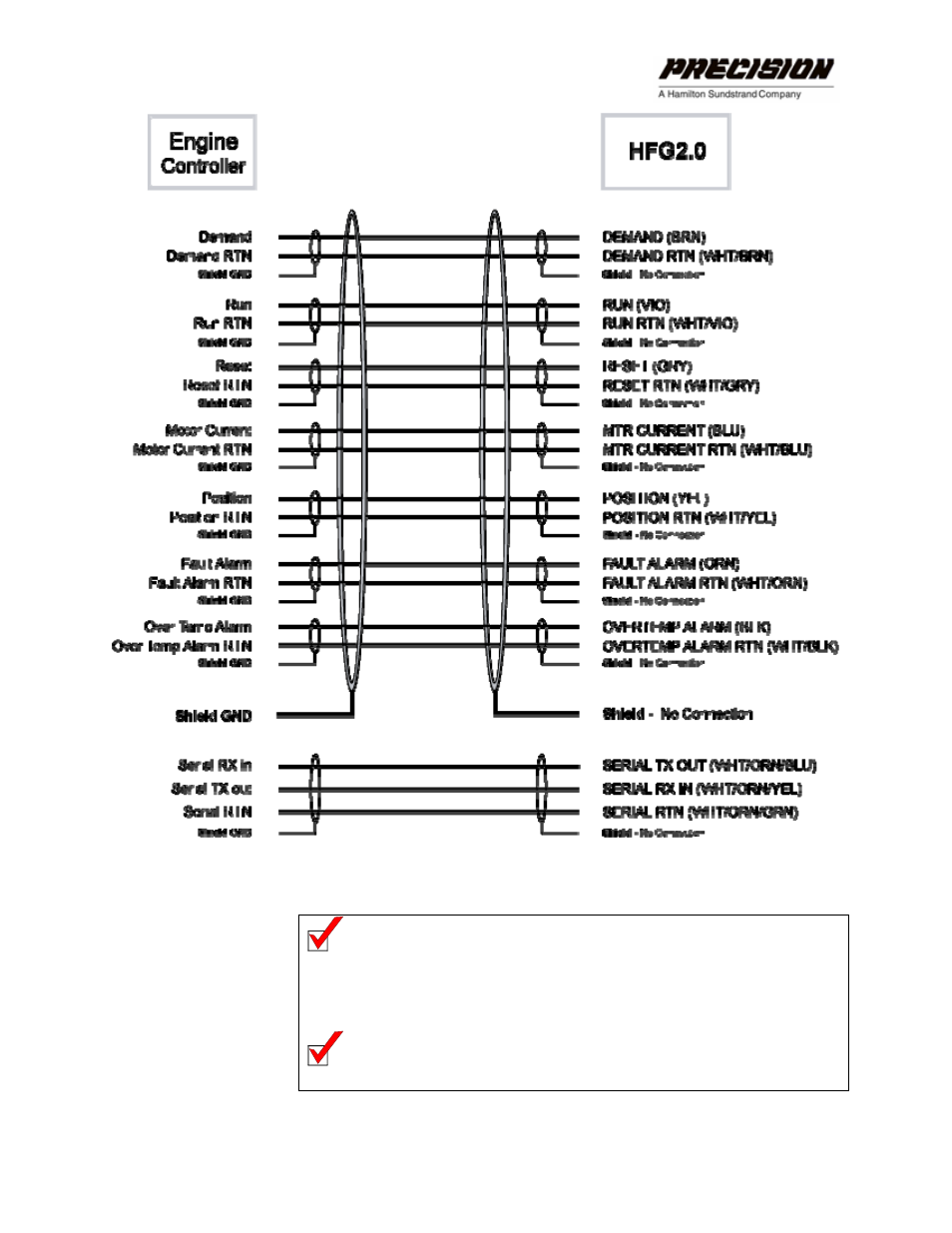
Figure 1-12: HFG2.0 System Signal Wiring Diagram
Note: For proper operation of the controller, the voltage between
the control inputs and the negative terminal of the power
supply should be below 200 VDC.
Note: The Serial Return is internally connected to the 120 VDC
input Return.
INSTALLING THE HFG2.0
19