Premier Mounts CTM-MS2 User Manual
Page 15
CTM-MS2
Installation Manual
Page - 15 -
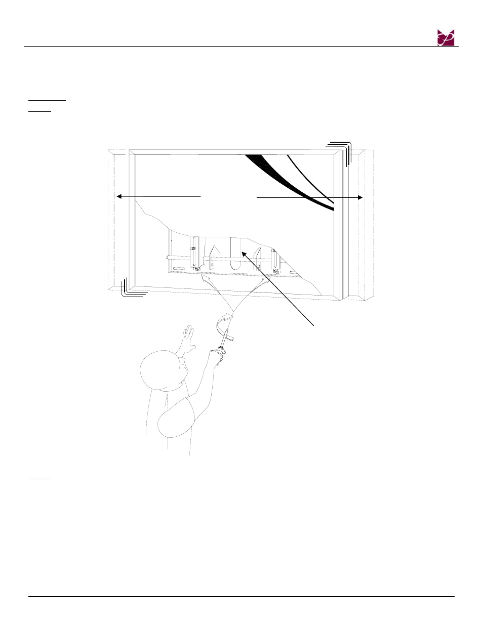
2.
Make any lateral shift adjustment and lock it by tightening the two (2) M6 x 30mm Phillips screws
found on the bottom of the mounting brackets. Use the foot leveler to adjust your plasma.
CAUTION:
Do not over tighten the M6 x 30mm screws to the rods (Figure 18).
NOTE:
To remove the display from the wall simply back off the M6 x 30mm screws using a Phillips
screwdriver and lift the unit of the wall carefully.
Figure 18
NOTE
:
Although not depicted in the illustrations shown above, the width of this wall mount will
encompass four wall studs (three studs if 24” apart).
Wall Plate
Lateral Shift