Operating instructions, Unpacking and cleaning, Extension cords – Porter-Cable 17-990X User Manual
Page 5: Foreword
Use proper extension cords. Make sure
your extension cord is in good condition and is a 3-wire
extension cord which has a 3-prong grounding type
plug and matching receptacle which will accept the
machine’s plug. When using an extension cord, be sure
to use one heavy enough to carry the current of the
machine. An undersized cord will cause a drop in line
voltage, resulting in loss of power and overheating. Fig.
D, shows the correct gauge to use depending on the
cord length. If in doubt, use the next heavier gauge. The
smaller the gauge number, the heavier the cord.
EXTENSION CORDS
FOREWORD
Delta Models 17-925 and 17-990X are 16½" variable speed drill presses. The Delta Models 17-925 and 17-990X have a
powerful ¾ HP motor which provides plenty of power for a variety of drilling jobs.
5
Fig. D
MINIMUM GAUGE EXTENSION CORD
RECOMMENDED SIZES FOR USE WITH STATIONARY ELECTRIC MACHINES
Ampere
Total Length
Gauge of
Rating
Volts
of Cord in Feet
Extension Cord
0-6
120
up to 25
18 AWG
0-6
120
25-50
16 AWG
0-6
120
50-100
16 AWG
0-6
120
100-150
14 AWG
6-10
120
up to 25
18 AWG
6-10
120
25-50
16 AWG
6-10
120
50-100
14 AWG
6-10
120
100-150
12 AWG
10-12
120
up to 25
16 AWG
10-12
120
25-50
16 AWG
10-12
120
50-100
14 AWG
10-12
120
100-150
12 AWG
12-16
120
up to 25
14 AWG
12-16
120
25-50
12 AWG
12-16
120
GREATER THAN 50 FEET NOT RECOMMENDED
OPERATING INSTRUCTIONS
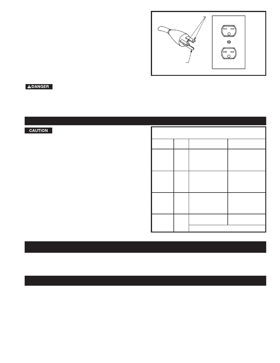
When converted for 230 volt operation, your drill press is
intended for use on a circuit that has an outlet like the
one illustrated in Fig. C. After conversion for 230 volts,
the drill press will have a grounding plug that looks like
the plug illustrated in Fig. C.
Make sure the drill press is connected to an outlet
having the same configuration as the plug. No adapter is
available or should be used when the drill press is
converted for 230 volts. If the drill press must be
reconnected for use on a different type of electrical
circuit, the reconnection should be made by qualified
service personnel; and after reconnection, the machine
should comply with all local codes and ordinances.
IN ALL CASES, MAKE CERTAIN THE
R E C E P TA C L E I N Q U E S T I O N I S P R O P E R LY
G R O U N D E D . I F Y O U A R E N O T S U R E H AV E A
Q U A L I F I E D E L E C T R I C I A N C H E C K T H E
RECEPTACLE.
CURRENT CARRYING
PRONGS
GROUNDING BLADE
IS LONGEST OF THE 3 BLADES
Fig. C
UNPACKING AND CLEANING
Carefully unpack the machine and all loose items from the shipping container(s). Remove the protective coating from
all unpainted surfaces. This coating may be removed with a soft cloth moistened with kerosene (do not use acetone,
gasoline or lacquer thinner for this purpose). After cleaning, cover the unpainted surfaces with a good quality household
floor paste wax.
NOTICE: THE MANUAL COVER PHOTO ILLUSTRATES THE CURRENT
PRODUCTION MODEL. ALL OTHER ILLUSTRATIONS ARE REPRESENTATIVE
ONLY AND MAY NOT DEPICT THE ACTUAL COLOR, LABELING OR
ACCESSORIES AND MAY BE INTENDED TO ILLUSTRATE TECHNIQUE ONLY.