Notice – Patton electronic 1045RC User Manual
Page 9
4.3.1 TERMINAL INTERFACE CONNECTION
The Model 1045RC is wired as a DCE, and allows for three possible
terminal interface connections:
•
RS-232C/V.24 (electrical) + DB-25 female (physical)
•
V.35/RS-530 (electrical) + DB-25 female (physical)
•
V.35 (electrical) + M/34 female (physical)
To select the appropriate
electrical
interface, please refer to
Section 3.1.4 of this manual. To select or construct a cable with the
appropriate
physical
interface pin-outs, please refer to the diagrams in
Appendix D and Appendix E of this manual.
4.3.2 TWISTED PAIR CONNECTION
The Model 1045RC supports communications between RS-232 or
V.35 devices at distances to 6 miles and data rates up to 64 Kbps. The
Model 1045RC is designed to operate in a closed data circuit with other
1045RCs or 1045 plug-in units.
To function properly, the Model 1045RC needs two twisted pairs of
unconditioned, dry metallic wire between 19 and 26 AWG (higher
number gauges may limit distance somewhat). Both shielded and
unshielded wire yield favorable results. Flat modular telephone type
cable, dial-up analog circuits or leased lines that run through
signal/equalization equipment are NOT acceptable. For further
information about acceptable wire grades, please refer to the diagram
in appendix B.
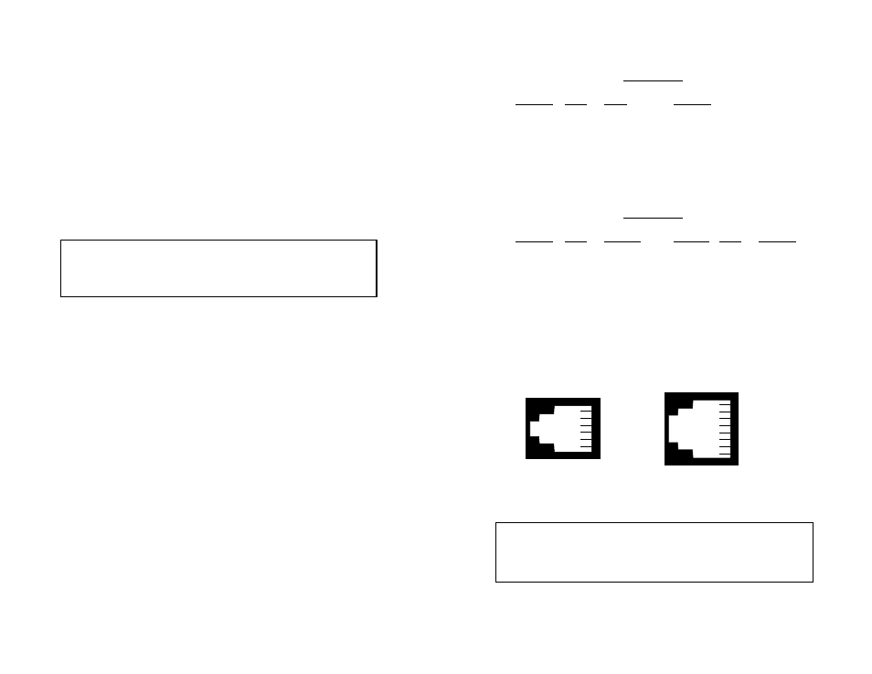
Point-to-Point Twisted Pair Connection
The 6-position RJ-11 and 8-position RJ-45 jack options for the
Model 1045RC are prewired for a standard TELCO wiring environment.
Connection of a 2-wire or 4-wire twisted pair circuit between two or
more Model 1045RCs requires a
crossover cable
as shown in the
following diagrams.
15
RJ-11/4-Wire
SIGNAL
PIN#
PIN#
SIGNAL
GND
†
1
6 .......................GND
RCV-
◊
2
4 .......................XMT-
XMT+
3
5 .......................RCV+
XMT-
4
2 .......................RCV-
RCV+
5
3 .......................XMT+
GND
6
1 .......................GND
RJ-45/4-Wire
SIGNAL
PIN#
COLOR
COLOR
PIN#
SIGNAL
GND
†
2
7.......................GND
RCV-
◊
3
5.......................XMT-
XMT+
4
6.......................RCV+
XMT-
5 3
RCV-
RCV+
6
4.......................XMT+
GND
7
2.......................GND
†
Connection to ground is optional
‡
Standard color codes—yours may be different
◊
The Model 1045RC is not sensitive to polarity
AT&T standard modular color codes
16
1 - Blue
2 - Orange
3 - Black
4 - Red
5 - Green
6 - Yellow
7 - Brown
8 - Slate
1 - Blue
2 - Yellow
3 - Green
4 - Red
5 - Black
6 - White
Notice!
Any modular twisted pair cable connected to the
Model 1045RC must be shielded cable, and the outer shield
must be properly terminated to a shielded modular plug on both
ends of the cable.
Notice!
Any terminal cable connected to the Patton Model
1045RC must be shielded cable, and the outer shield must be
360 degree bonded–at both ends–to a metal or metalized
backshell.